MIDI output voltage: WIDI Master is getting hot

Other than a design flaw in the WIDI, I would find it hard to believe that so many WIDI Master owners would run into the same problem with this specific configuration. So one of the devices is not working right if the WIDI heats up at 5V. Does anyone have an Axe-Fx 3 to try so they could see if that works differently? Also why 3.3V on Axe-3 vs 5V on FM3?

There seems to be a new firmware 1.3.0.7 out for the WIDI and I tried updating both my dongles to use that and no change. It doesn't take much time for the dongle to really heat up after FM3 is started.

Personally I would not be at all surprised if the problem is on CME's side because their WIDI app software is pretty flaky, firmware updates are not done that great and getting the groups feature to work is equally messy.
 
Last edited:
All FM3 MIDI users are having the exact same problem, i also chatted with @Edrod who has the same issue.
Your argument would mean that all FM3 units are faulty (above 5V) which would be very unusual.
Also: @Ben Lewry measured 5V and he is getting a hot MIDI master as well, so basically proved that the FM3 is working fine.

My argument is not that all FM3 units are faulty. I was just suggesting to measure the voltage and take a picture, to prove it to the WIDI manufacturer. My suspicion is that the WIDI is not designed to support 5V without getting hot, despite of what the manufacturer says. But, since he is offering a replacement if it gets hot with 5V, I would just send it back for a replacement.
 
I sent CME a link to this post to check the measurement.
A replacement will (in this state) not make a difference because all FM3 WIDI users are having the same issues and if we can exclude the FM3 as a problem in this setup, all WIDI units have to be faulty.

Another approach: Did anyone hook up the WIDI dongle to another 5v unit? I only have 3.3V devices ..
 
I connected the WIDI unit up to 5v on my benchtop power supply. It overheated immediately.
Then I thought to connect it through a 220ohm resistor, which is what the official midi specification calls for.
With the 220 ohm resistor in series with the 5v supply, the WIDI Master runs fine and cool.
So now I'm wondering how the FM3 powers the MIDI Out?
Perhaps it uses a different method that omits the current limiting resistor?

I tested the current available from the Midi Out pin 4 of the FM3 and it shorted the unit.
Then through a 220ohm resistor I get 22mA, which is expected using Ohms law.

I don't know much about alternate ways to power MIDI, but I'm guessing the FM3 is
not using a 220 ohm current limiting resistor before the 5v pin.
This allows the Widi Master to draw too much current and overheat.

Full Disclosure:
I design and build guitars for Visionary Instruments. These guitars are specifically designed to control the AxeFX and FM3 with midi.
I'm absolutely in love with everything Fractal and I want to see all this gear play well together.
 
Last edited:
Well, someone did his homework :D Super interesting stuff!
So, the FM3 is maybe missing something, right? Is this 220 ohm resistor "required" in the MIDI specification?
Does the Axe III has something like this on board? ...
 
Hi, I just ran into this issue as well.
I checked Midi Out voltages with a multimeter.
The voltage from the AxeFX III MIDI OUT is 3.3v
The voltage from the FM3 MIDI OUT is 5v

Inside the Widi Master, there's a small IC that is screaming hot to the touch at 5v.
Our CTO answered your question:

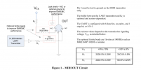
Our design is based on the hardware MIDI specification.
The specification shows a serial resistor is present on MIDI output of the instrument.

As mentioned in the MIDI Out spec, on a 5V MIDI output, the resistor is 220R, while it is 33R for a 3.3V MIDI out.
Because the WIDI Master operates a 3.3V internally, we cannot add a new resistor before the regulator (which is by the way a programmable voltage reference), this allows us to support 3.3V MIDI.

Our design assumes the connected instrument follow the MIDI specification.
If the above serial resistor is not present in the instrument, or if its value differs from the specification, it could indeed result in unexpected behavior.

When you apply your external power supply directly to the WM input, you do not have this serial resistor between the source and the WM, this results in the WM internal voltage equals to the voltage you are applying, that makes the IC hot and could end in a destroyed IC.MMA MIDI Out spec.png
 
So would the solution to this be to make for example a short MIDI adapter cable that includes a 220 ohm resistor in series going to pin 4 which seems to be the 5V?

Like this: FM3 MIDI out -> Adapter MIDI plug (male) -> 220 ohm resistor in cable going to pin 4 -> Adapter MIDI plug (female) -> CME WIDI Master
 
Last edited:
So would the solution to this be to make for example a short MIDI adapter cable that includes a 220 ohm resistor in series going to pin 4 which seems to be the 5V?

Like this: FM3 MIDI out -> Adapter MIDI plug (male) -> 220 ohm resistor in cable going to pin 4 -> Adapter MIDI plug (female) -> CME WIDI Master
Yes, we think that should work. Or you can make a cable with 220 ohm resistor for WIDI Jack, that will be simple.
 
Interesting - i don't understand why the FM3 is missing something which is defined by the MIDI Standard - but - i really want to make this work - Thanks @CME WIDI for taking the time and taking this serious.

I can solder - but i do need to know which parts are required ... i can only solder "by guide" :/
If anyone is awesome enough to make a few pictures while soldering his cable, i would HIGHLY appreciate it (and send a digital cookie ;)
Something like this, correct me if I am wrong:
  • MIDI 5-pin DIN connector (male)
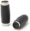
  • MIDI 5-pin DIN connector (female)
  • 220 ohm resistor
  • Short cable with 3 individual cables bundled inside
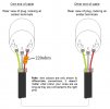
Then you can see on this MIDI pinout which is the 5V line, in this case pin 4. Then you just solder the 220 ohm resistor to pin 4 on e.g the male connector, the other end to the pin 4 cable and assemble the rest of the cable pin to pin.

Easiest is probably to just buy a short MIDI cable and disassemble it enough to add the resistor to the pin 4 cable, put some heatshrink on it and reassemble. The resistor might be just small enough to fit inside the connector assembly.
 
Last edited:
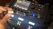
So... I tried the adapter trick, adding a 220ohm resistor.
It works!

I also tested the inline resistor with a standard wired connection to MIDI 5 pin on my computer interface.
It still works as well.
This is good news, as you could potentially add the resistor inside the FM3 without effecting
the performance of the wired MIDI out in other scenarios.

It would be great to get confirmation from the FM3 engineers though. ;)

20210601_132132.jpg
 
Sounds great! Can you write your cable connections? Like, which pins are in use etc ...
Would be interesting to open up something like this and ad the resistor :) ...

1622570284586.png
 
Are all FM3's affected by this? I'm tempted to open my unit up and check for this 220 Ω resistor.
 
Back
Top Bottom