Ethercon for the MFC 101 - The missing link

Why not install the same jack in the same way as the MKII has? I should have used a black EtherCon Jack and there will be a little bit of the old square cutout showing on the bottom.
P1020372.jpg
 
Why not install the same jack in the same way as the MKII has? I should have used a black EtherCon Jack and there will be a little bit of the old square cutout showing on the bottom.
View attachment 17905

I've thought about doing that. The clips that hold the cable in, broke off on mine. I can send it to FAS but i'd rather have etherncon =(
 
Hey Patzag,
Your method is what inspired me to approach the problem so, thanks! My Bass player tripped on my cat 5 cable a couple of weeks ago cracking the jack and I didn't like using the MIDI cable. My Brother has the old MFC and wants to pay me $50 + parts to convert his. Since I work on circuit boards and have a desoldering iron, this method made sense to me as the old cat 5 jack has the identical horizontal PCB pin configuration as the horizontal EtherCon jack so there is no possibility of wiring it improperly.
 
So that little adapter is what inspired the Mark III revision?

I think it inspired the Mark II, not the Mark III, which uses "FASLINK" a fancy system of transmitting power and midi over an XLR cable.

What I'm still waiting for is the expansion module.
 
Yes, I was too impatient to buy the right drill bit so I took my dremel tool to it. I am going to buy a drill bit before I do my Brothers'.
 
Performed this mod last night with some mixed results and eventually got there. I'll post an in depth description and some pics soon (have to get them loaded up off my phone). I've done a "for now" job as I'm about to go out on tour (I'm an idiot for modding it 3 days before we leave without any major chance to test it other than playing at home), so the cabling I used is held to the chassis with masking tape and cable ties for now and the soldering job I did looks a little funky, but it works for the time being.

as mentioned, pics up soon
 
OK, here we go:

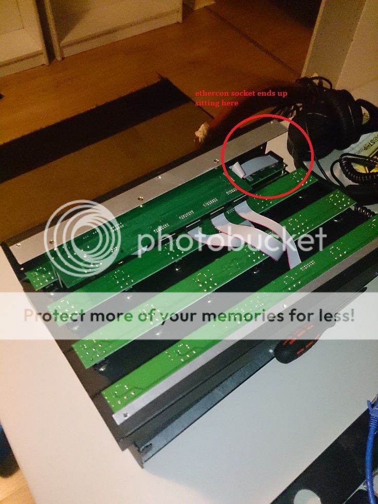
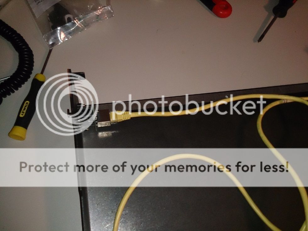
Firstly, I wanted my ethercon connector to be mounted on the side, this presents a few problems in itself because of space restrictions and the fact that you need to run the cable from one part of the chassis to another. Also, I'm running to a 1u blanking plate as has been suggested earlier in order to have ethercon at both ends for no other reason than I want to. So after opening it up and checking things out, I found a spot I could put it.

3_zpsc6fb40db.jpg

1_zpsfcc7016e.jpg

12_zpsb8524de8.jpg


While I was at it, I marked out the holes to cut out on my blanking panel - I marked spots for two XLR panel mount sockets as well, but didnt mount them yet (about to go on tour, dont want more to worry about right now).

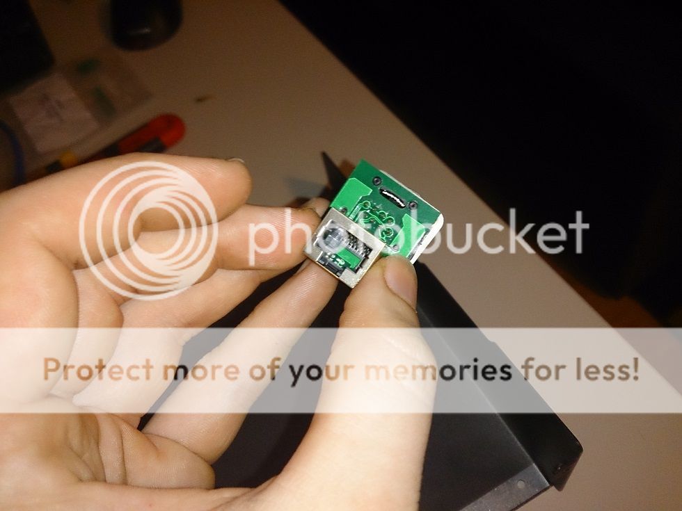
While in side, I detached the panel the ethernet socket is attached to and basically just made it accessible to solder. I couldn't get my head around the different protocols of cat5 cabling - Why cant these things just be simple?!!?!!, and so I basically wired it point to point based off what pin would be touching what contact. This worked, but only briefly and would end up with the name timeout error after a few seconds or button presses, no names of patches, IA switches or scene changes were displayed either. I eventually worked out that "B" protocol entailed changing two of the wire positions, so I did that, tested everything and happy days.

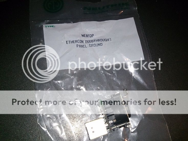
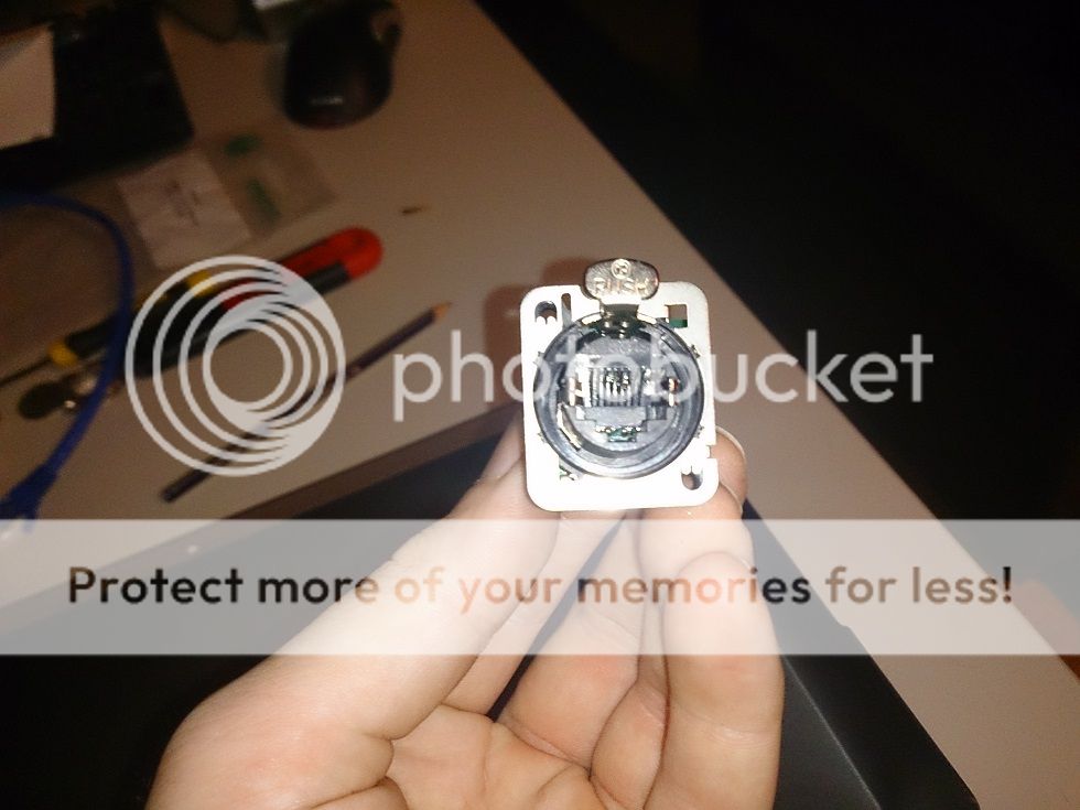
The ethercon connectors I bought are a panel mount, pass through style, meaning the only soldering I had to do was on the board inside the MFC itself. This was insanely handy

6_zps8e95d783.jpg

4_zpsdd008d15.jpg

5_zpsb0b6562a.jpg


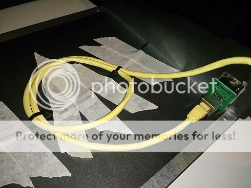
I used a 3 foot long cat 6 cable inside it and for now, I've had to just cable tie it and use masking tape to try and prevent it from moving around inside too much. I needed that kind of length as mounting to the side of the board means each end of the cable is mounted to a different part of the chassis, potentially causing problems when opening the unit (which I'll try to avoid anyway, but I'll need to re-fix everything once I'm back), this way, theres plenty of room to keep the ends attached and terminated without having to worry about it pulling at anything.

11_zpsdcdadfcc.jpg

7_zps547e0c4a.jpg

(like I said, it's not pretty, but its functional until I get back and can source some cable tie mounting points and do things properly)

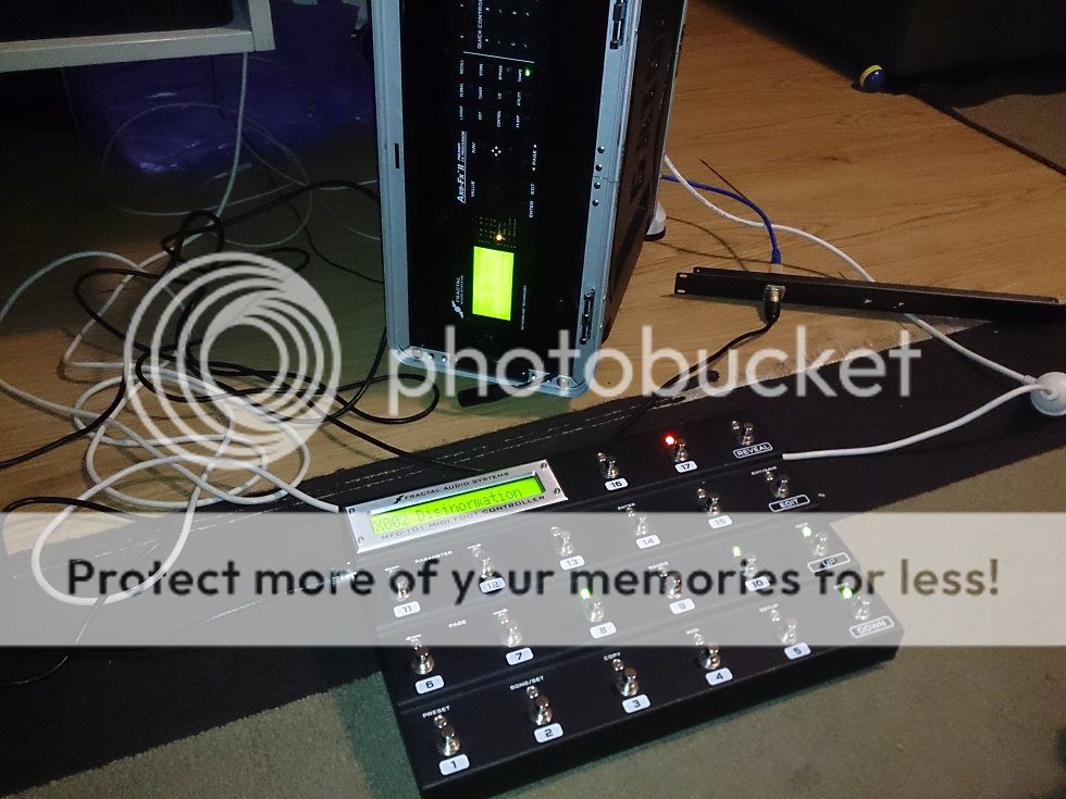
Here's the finished product in action, quite happy with how it all turned out, but as mentioned, I'll get in there and tidy things up once I'm back home long enough to really play with things.

9_zps6de78715.jpg


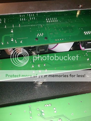
Also, whilst I was in there, I found another RJ45 socket, I got excited for a second, thinking I could just plug one end of the cable into the pass-through ethercon and the other into this, but it's a small, phone style RJ45 - interessted to know what it's purpose is...??

14_zpsf533d62d.jpg


If you have any questions about the mod, I can try and help
 
Last edited:
So.... why hasn't this been done before we buy them?

If you bought a mark 2 (now discontinued until the 3 comes out, problem is, no one knows how far off they are), an ethercon port comes as standard on it (not sure of other differences), but living in australia, getting a mark 2 was going to be tricky and waiting for a 3 would probably take too long, so modding is the best option in my situation.
 
You're totally right.

I've not dared to open the box, and protected the vulnerable rear of my MFC underneath a row of extension switches, with the heavy-duty connector velcro'd to the board where bass guitarists like to trample.
 
Back
Top Bottom