Patzag
Fractal Fanatic
The MFC 101 is a fantastic foot controller. Well built, sturdy, fabulous software, integrate extremely well with the Axe II.
The only thing which makes it one small step removed from a touring unit is an Ethercon connector. In fact, two would be great so a touring musician could have two in different locations of the stage.
But for now, one would be awesome.
Having bought mine used, and therefore having forfeited my warranty from the get-go, I decided to, so to speak, make the jump and install that missing link. I figured you might want to know about it so here goes.
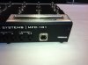
1. Dismantling the unit is a matter for a few screws so I won't comment on that.
2. I removed the main logic board, the screen and all connectors to the foot switch.
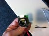
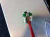
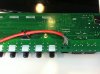
3. I used a short Cat5 cable and soldered one end to the logic board, using the standard B protocol of color coding.
4. I checked continuity and ensured there were no shorts (I did this about 8 times throughout the procedure)
5. I then cable tied the cable to the board so that there would be NO internal strain on it no matter what.
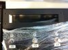
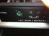
6. I used a professional panel-mount Neutrik Ethercon connector with punch-block inserts and routed the cable to the proper pins.
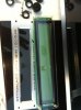
7. Using a hole-saw and a reamer, a perfectly fitting hole was made right under the screen on the back panel to receive the panel-mount connector.
8. Tested the unit, put it back together and voila.
9. I used the opportunity to clean the "glass" over the display which had a rather large "bubble" in it. Invisible when tuned on but still offended my sense of propriety!
Here are a few shots:
The only thing which makes it one small step removed from a touring unit is an Ethercon connector. In fact, two would be great so a touring musician could have two in different locations of the stage.
But for now, one would be awesome.
Having bought mine used, and therefore having forfeited my warranty from the get-go, I decided to, so to speak, make the jump and install that missing link. I figured you might want to know about it so here goes.
1. Dismantling the unit is a matter for a few screws so I won't comment on that.
2. I removed the main logic board, the screen and all connectors to the foot switch.
3. I used a short Cat5 cable and soldered one end to the logic board, using the standard B protocol of color coding.
4. I checked continuity and ensured there were no shorts (I did this about 8 times throughout the procedure)
5. I then cable tied the cable to the board so that there would be NO internal strain on it no matter what.
6. I used a professional panel-mount Neutrik Ethercon connector with punch-block inserts and routed the cable to the proper pins.
7. Using a hole-saw and a reamer, a perfectly fitting hole was made right under the screen on the back panel to receive the panel-mount connector.
8. Tested the unit, put it back together and voila.
9. I used the opportunity to clean the "glass" over the display which had a rather large "bubble" in it. Invisible when tuned on but still offended my sense of propriety!
Here are a few shots: