Multi-Screen DIY controller

Absolutely excited to build one of these.
I have my first Axe FX 3 on the way. Long time software engineer, also have experience building things in CAD for metal fabrication, PCB/electronics fab, etc. This looks like the perfect blend.

+1 for the Teensy. I have a ton of the 3.2s and they've been rock solid. Interestingly enough, if using an ESP32, we could get the processing power, same arduino programming interface and have wireless connectivity for things like app control (though that wifi chip is pretty noisy).

I've loved sifting through the code and conversation!
-- Jimmy
Hey there, welcome

Thats is great to hear. I will create the thread this evening to get it started. In the meanwhile you could check out @prongs_386 his github for his code and for my build see this github to sift through some more code 😅

Cheers 🍻
 
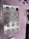
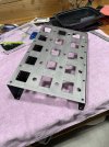
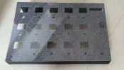
Another option you can think about for perfectly square holes is the rabbit hole I went down. I sent my Corel EPS drawing to sendcutsend.com, they cut it out of .100 aluminum plate - 63 bucks shipped. Cutting apart the case, drilling and laying out the small holes was exciting. This is for a a smaller form factor controller that I will use with my FM9. I scrapped the project for a while as I had some upcoming gigs that I needed to relearn the songs for...
 

Attachments

  • IMG_6322.jpeg
    IMG_6322.jpeg
    1.3 MB · Views: 26
  • IMG_6314.jpeg
    IMG_6314.jpeg
    1.1 MB · Views: 27
Another option you can think about for perfectly square holes is the rabbit hole I went down. I sent my Corel EPS drawing to sendcutsend.com, they cut it out of .100 aluminum plate - 63 bucks shipped. Cutting apart the case, drilling and laying out the small holes was exciting. This is for a a smaller form factor controller that I will use with my FM9. I scrapped the project for a while as I had some upcoming gigs that I needed to relearn the songs for...
Hey there

You US guys got all the good stuff for allmost for free. Here in europe, have to go all DIY to save money for the expensive lives we live here. If it would be possible for me, I would laser cut too, its professional looking

Cheers 🍻
 
Another option you can think about for perfectly square holes is the rabbit hole I went down. I sent my Corel EPS drawing to sendcutsend.com, they cut it out of .100 aluminum plate - 63 bucks shipped. Cutting apart the case, drilling and laying out the small holes was exciting. This is for a a smaller form factor controller that I will use with my FM9. I scrapped the project for a while as I had some upcoming gigs that I needed to relearn the songs for...
This setup will work with my 8.1 program. You wont have the tuner and the bank up/down (+/-10) but you could set the tuner on a diffrent button. The software from @prongs_386 would work perfectly with this form factor.
 
You work at RJM?
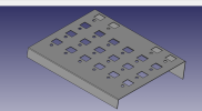
I do not! I do, however love RJMs format for midi floor controllers and the stuff they've built. So the CAD you're seeing is something I'm laying out that IS the RJM form factor, but with different innards. RJM, I believe, uses a chip-on-glass (COG) display without a backlight, and handles the RGB using LEDs that surround the display glass with a set of plastic light diffusers. It's impressive, but is a bit more work to engineer. So I plan on using the 1.8" SPI displays that you guys have used and an ESP32. I did debate doing a touch screen based system using a raspberry pi (I have loads of experience with embedded operating systems, so designing something for it wouldn't be hard at all).

For my day job, I mostly work on software for the automation/provisioning of cloud infrastructure. So the chance to work on hardware/software for music is a bit more zen compared to what I work on during the day :)
Those are a lot of screens and buttons. Are you planning on using multiple controllers for the build? Because one ESP32 would not have enough pins to connect
 
Those are a lot of screens and buttons. Are you planning on using multiple controllers for the build? Because one ESP32 would not have enough pins to connect
Good question! I have some MCP23017 I/O expanders so I can control the chip select lines on up to 16 displays with only the I2C bus. I can chain 2 of these together. Another option would be to matrix the switches, but that's overly complicated due to the fact that we don't need strict realtime control and limited I/O. So I could also clock those bits in with shift registers to cut down on the amount of I/O. I've done multi-controller setups in the past, but this doesn't seem to warrant that level of complexity.

That looks great - what are you thinking for thickness? I went with .100 to ensure no flexing with all of the screen cutouts
For .104" mild steel, SendCutSend was quoting something crazy like $166 per part ($130 with a quantity of 2+). However .059" is $122 each ($97 @ 2+). This is the thickness that things like a Voodoo Lab Ground Control use. I can also have them put standoffs in the middle for additional support to keep the PCBs from flexing. For something like 3 standoffs down the middle, you should be able to double the strength of the material. I haven't priced out OSH Cut yet, but they can be cheaper on certain things.

Anyone ever take a look at the VController? Looked pretty interesting!
 
Last edited:
Good question! I have some MCP23017 I/O expanders so I can control the chip select lines on up to 16 displays with only the I2C bus. I can chain 2 of these together. Another option would be to matrix the switches, but that's overly complicated due to the fact that we don't need strict realtime control and limited I/O. So I could also clock those bits in with shift registers to cut down on the amount of I/O. I've done multi-controller setups in the past, but this doesn't seem to warrant that level of complexity.
I needed more analog pins... that seems to be easy with this addon: CD74HC4067
You opened a new vision for me how to approach my new setup.. awesome! thanks

Cheers 🍻
 
Where do you live that they are so expensive?

And nice job, allot of work
Holland..
Its 130 euro's only to program the cnc and then pay for the time and tax. Had to pay 185 euro's for a single box. The second and next would be 50 euro extra.

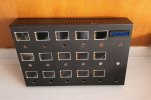
I did it with the jigsaw, worked out pretty well
20230226_162032.jpg

Oh, and to make it more glamorous, Ive added a LykeIII sparkle top.
Still under construction though 😉

20230306_125154.jpg

Cheers 🍻
 
Last edited:
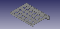
So I had a bit to work on my build over the past week. I'm about finished with the sheet metal CAD. It's directly modeled after the RJM Mastermind GT16. This was/is a great chance for me to scratch multiple itches in terms of electrical, mechanical and software creativity. Looks like the case will be ~$80USD to get made which isn't terrible. I resized the enclosure to a 17 inch width, 12 inch height so it could fit inside of a rackmount tray. I use an 8U Gator case with wheels to transport my rig, so this means the controller can sit on the bottom tray for transport like my old GCX used to.

Screenshot 2023-03-04 120655.png

Displays will be connected to a single PCB per row. So each PCB can connect either 6 1.8 inch displays and footswitches or 4 1.8 inch displays and a center 3.5 inch touch display. This limits the number of parts/PCBs to a single part number for all of the rows and can be fulfilled in a single JLCPCB sample order. Yay savings.

Each display row will be connected via ribbon cable to a control board that also hosts the rear I/O panels. The rear I/Os are your standard EXP1-4 jacks, USB type B port, midi in/out/thru, power (with reverse polarity protection) and aux foot switches.

The central processor is an ESP32 running at 40MHz. SPI bus clock, master and slave data are controlled directly from the ESP32. CS lines are strobed via I2C and MCP23017 I/O expander chips. Each row board has its own I/O expander that handles 6 CS lines and 6 footswitches. I2C addresses are set via dipswitches on each board. That means that each ribbon cable merely carries MISO, MOSI, CLK, GND, SDA and SCL. Power rails will have their own dedicated connector to keep noise down (and allow for thicker gauge cable).

The touch display will be powered by a raspberry pi pico and will also be on the SPI bus, receiving commands from the ESP32.

Testing the Software

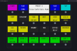
While I'm waiting for my displays to come in and doing final fitment tests before I send the metal out for fab, I've been testing the midi interface between my PC and the Axe FX III. I designed a WebMIDI-based editor that allows me to test the logic both in the foot controller program as well as the communications back and forth with the AxeFX III. While it's in JavaScript, it's not all a waste of time. The foot controller will all be C++ code, BUT this interface can later serve as an editor tool much the same way as Axe Edit or the RJM editor works. Plug the USB into your computer/foot controller, edit presets in the app, flash them to the board.

This interface serves multiple functions.
1. Mostly testing the logic/button presses/ergonomics with how I want the board to function
2. Testing the SysEX messages as well as standard midi commands going back/forth to the Axe FX III unit.
3. Sniffing the communications/midi data being exchanged between AxeEdit and the Axe FX III. This is useful for debugging.

I've got presets, scene control, tuner engagement, instant access effects, and expression emulation implemented. I still need to implement tap tempo, and I'll be experimenting with split device controls so I can control both my AxeFX III and my DAW (reaper) with one board, most likely using the buttons from unused scenes/FX.

Screenshot 2023-03-04 123733.png


All in all, a great week of productivity and this has been fun to work on thus far!
 
So I had a bit to work on my build over the past week. I'm about finished with the sheet metal CAD. It's directly modeled after the RJM Mastermind GT16. This was/is a great chance for me to scratch multiple itches in terms of electrical, mechanical and software creativity. Looks like the case will be ~$80USD to get made which isn't terrible. I resized the enclosure to a 17 inch width, 12 inch height so it could fit inside of a rackmount tray. I use an 8U Gator case with wheels to transport my rig, so this means the controller can sit on the bottom tray for transport like my old GCX used to.

View attachment 117106

Displays will be connected to a single PCB per row. So each PCB can connect either 6 1.8 inch displays and footswitches or 4 1.8 inch displays and a center 3.5 inch touch display. This limits the number of parts/PCBs to a single part number for all of the rows and can be fulfilled in a single JLCPCB sample order. Yay savings.

Each display row will be connected via ribbon cable to a control board that also hosts the rear I/O panels. The rear I/Os are your standard EXP1-4 jacks, USB type B port, midi in/out/thru, power (with reverse polarity protection) and aux foot switches.

The central processor is an ESP32 running at 40MHz. SPI bus clock, master and slave data are controlled directly from the ESP32. CS lines are strobed via I2C and MCP23017 I/O expander chips. Each row board has its own I/O expander that handles 6 CS lines and 6 footswitches. I2C addresses are set via dipswitches on each board. That means that each ribbon cable merely carries MISO, MOSI, CLK, GND, SDA and SCL. Power rails will have their own dedicated connector to keep noise down (and allow for thicker gauge cable).

The touch display will be powered by a raspberry pi pico and will also be on the SPI bus, receiving commands from the ESP32.

Testing the Software

While I'm waiting for my displays to come in and doing final fitment tests before I send the metal out for fab, I've been testing the midi interface between my PC and the Axe FX III. I designed a WebMIDI-based editor that allows me to test the logic both in the foot controller program as well as the communications back and forth with the AxeFX III. While it's in JavaScript, it's not all a waste of time. The foot controller will all be C++ code, BUT this interface can later serve as an editor tool much the same way as Axe Edit or the RJM editor works. Plug the USB into your computer/foot controller, edit presets in the app, flash them to the board.

This interface serves multiple functions.
1. Mostly testing the logic/button presses/ergonomics with how I want the board to function
2. Testing the SysEX messages as well as standard midi commands going back/forth to the Axe FX III unit.
3. Sniffing the communications/midi data being exchanged between AxeEdit and the Axe FX III. This is useful for debugging.

I've got presets, scene control, tuner engagement, instant access effects, and expression emulation implemented. I still need to implement tap tempo, and I'll be experimenting with split device controls so I can control both my AxeFX III and my DAW (reaper) with one board, most likely using the buttons from unused scenes/FX.

View attachment 117107


All in all, a great week of productivity and this has been fun to work on thus far!
This is 1000% awesome! Major props!

I might want one myself even, perhaps

So cool.
 
So I had a bit to work on my build over the past week. I'm about finished with the sheet metal CAD. It's directly modeled after the RJM Mastermind GT16. This was/is a great chance for me to scratch multiple itches in terms of electrical, mechanical and software creativity. Looks like the case will be ~$80USD to get made which isn't terrible. I resized the enclosure to a 17 inch width, 12 inch height so it could fit inside of a rackmount tray. I use an 8U Gator case with wheels to transport my rig, so this means the controller can sit on the bottom tray for transport like my old GCX used to.

View attachment 117106

Displays will be connected to a single PCB per row. So each PCB can connect either 6 1.8 inch displays and footswitches or 4 1.8 inch displays and a center 3.5 inch touch display. This limits the number of parts/PCBs to a single part number for all of the rows and can be fulfilled in a single JLCPCB sample order. Yay savings.

Each display row will be connected via ribbon cable to a control board that also hosts the rear I/O panels. The rear I/Os are your standard EXP1-4 jacks, USB type B port, midi in/out/thru, power (with reverse polarity protection) and aux foot switches.

The central processor is an ESP32 running at 40MHz. SPI bus clock, master and slave data are controlled directly from the ESP32. CS lines are strobed via I2C and MCP23017 I/O expander chips. Each row board has its own I/O expander that handles 6 CS lines and 6 footswitches. I2C addresses are set via dipswitches on each board. That means that each ribbon cable merely carries MISO, MOSI, CLK, GND, SDA and SCL. Power rails will have their own dedicated connector to keep noise down (and allow for thicker gauge cable).

The touch display will be powered by a raspberry pi pico and will also be on the SPI bus, receiving commands from the ESP32.

Testing the Software

While I'm waiting for my displays to come in and doing final fitment tests before I send the metal out for fab, I've been testing the midi interface between my PC and the Axe FX III. I designed a WebMIDI-based editor that allows me to test the logic both in the foot controller program as well as the communications back and forth with the AxeFX III. While it's in JavaScript, it's not all a waste of time. The foot controller will all be C++ code, BUT this interface can later serve as an editor tool much the same way as Axe Edit or the RJM editor works. Plug the USB into your computer/foot controller, edit presets in the app, flash them to the board.

This interface serves multiple functions.
1. Mostly testing the logic/button presses/ergonomics with how I want the board to function
2. Testing the SysEX messages as well as standard midi commands going back/forth to the Axe FX III unit.
3. Sniffing the communications/midi data being exchanged between AxeEdit and the Axe FX III. This is useful for debugging.

I've got presets, scene control, tuner engagement, instant access effects, and expression emulation implemented. I still need to implement tap tempo, and I'll be experimenting with split device controls so I can control both my AxeFX III and my DAW (reaper) with one board, most likely using the buttons from unused scenes/FX.

View attachment 117107


All in all, a great week of productivity and this has been fun to work on thus far!
Holy S#it wow.... how do you separate the boys from the men? This ^^

Awesome man..


Cheers 🍻
 
Hey there DIY enthusiasts

My Arduino IDE version was 1.8.something, and just discovered V2.0.4 <--- You need this if you havn't

The firewall warning for the mdsn-discovery can easily be bypassed to change the name of the msdn-discovery.exe in the local/arduino15/packages/builtin/tools/msdn-discovery/1.0.8/ if you dont have a OTA board.

Cheers 🍻
 
e project for a while as I had some upcoming gig
Whoa, I thought of using Send Cut Send or Ponoko at the suggestion of a prior co-worker (on the Fusion 360 team) but just assumed something big enough for a foot controller would cost hundreds. $63?!?!?! No brainer. I'll be doing some enclosure redesign and get right onit.
 
I do eventually want mine to use the graphic images from or similar to the unit and Axedit too. So the idea is if I assign a controller to a momentary footswitch the TFT display above it will show that block image as background and the control it's assigned to.

I know that won't always work though because you can assign one controller to many things in the preset... so maybe not ;-) Just need to figure out a cool way to handle it.
 
Back
Top Bottom