DIY Axe-Fx Foot Controller for $50 (Open Project)

I verified that my MIDI to USB adapter was functioning (used a keyboard and a midi monitor to mark sure it was hearing).

I’m not getting any MIDI messages at all from the Mega. I pulled everything off the bread board and started over. There’s a chance I may have had the 4 and 5 pins mixed up previously, but they’re good now—I hope that didn’t fry anything! Especially on the Axe side.

I did find out that the LCD does reflect looper commands when I connect the relevant pins to ground , so it seems like the code did successfully install.
 
Hey there

Any chance you ever used the serial console in the IDE? I saw a debug line that sends info to the console. Hook the arduino to the pc, start the console, that will restart the arduino and see if the code is working. If so and the data is still not transferred from the fractal to the arduino you know its a midi thing
 
Last edited:
Hey there

Any chance you ever used the serial console in the IDE? I saw a debug line that sends info to the console. Hook the arduino to the pc, start the console, that will restart the arduino and see if the code is working. If so and the data is still not transferred from the fractal to the arduino you know its a midi thing
I may be doing something wrong, but I gave it a try. The serial monitor is blank unless I test one of the pins to ground, which then causes it to display “Switch 5 pressed” and so on.

I really appreciate your help!
 
Hey guys and gals!

I decided to try my hand at this project, but I'm a complete fish out of the water when it comes to any of this stuff. I've been trying to find a diagram with the connections, but I can only seem to find the one that uses the Arduino Due, instead of this one that uses the Mega. Am I blind and missed it, or should I use the Due (the one on github by kmcgain) as a starting point?

Thanks a lot!
Hey there

What fractal product are you gonna use it for?
 
Hey guys and gals!

I decided to try my hand at this project, but I'm a complete fish out of the water when it comes to any of this stuff. I've been trying to find a diagram with the connections, but I can only seem to find the one that uses the Arduino Due, instead of this one that uses the Mega. Am I blind and missed it, or should I use the Due (the one on github by kmcgain) as a starting point?

Thanks a lot!

Hi. The wiring is quite straightforward without the need of an electric diagram. From the first post:

Switches:

Common terminal of all switches connected to ground
The 15 Switches are connected to pins n. 22, 24, 26, 28, 30, 32, 34, 36, 38, 40, 42, 44, 46, 48, 50
http://www.instructables.com/id/Arduino-Button-with-no-resistor/


LEDs:

  • Cathode (short leg) connected to ground
  • Anode (long leg) connected through a 220 Ohm resistor to pins n. 23, 25, 27, 29, 31, 33, 35, 37, 39, 41, 43, 45, 47, 49, 51
https://www.arduino.cc/en/tutorial/blink

What display do you plan to use?
Let us know if you need further details
 
Hey thanks for the quick reply!
I am going to use the 20x4 I2C LCD which should be delivered within the week. I downloaded v11.01 and finally managed to make it Verify and Upload into the board after 2 hours of trying to figure out the libraries to use and how to use them (again, completely new to this ^^; ).
For now I'll try to hook up everything that I have (i.e switches, 5 pin DIN) and see if it works.
If I'm not mistaken, the whole thing is powered via USB, right?
 
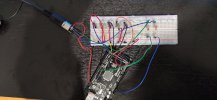
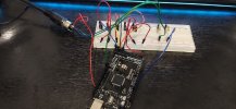
So here's my progress of my little abomination so far :D
Pic 01.jpgPic 02.jpg

I opened the Serial Monitor tool and it seems to register the Switch presses alright, which is a great sign. Unfortunately, nothing seems to happen on the Axe. I believe I have the connections on the DIN correct as well:
[+5V] -> [Blue cable] -> [resistor] -> [pin 4] (I think. The one to the left of the middle pin, when looking at the DIN from the cable side/back side)
[GND] -> [Red cable] -> [pin 2] (middle pin)
[TX0->1] -> [Green cable] -> [pin 5] (the one to the right of the middle pin, when looking at the DIN from the cable side/back side)

The soldering job on the DIN is not the best, but I'm pretty sure there is nothing touching something that it shouldn't be touching.

Any ideas?

Thanks
 
So here's my progress of my little abomination so far :D
View attachment 98905View attachment 98906

I opened the Serial Monitor tool and it seems to register the Switch presses alright, which is a great sign. Unfortunately, nothing seems to happen on the Axe. I believe I have the connections on the DIN correct as well:
[+5V] -> [Blue cable] -> [resistor] -> [pin 4] (I think. The one to the left of the middle pin, when looking at the DIN from the cable side/back side)
[GND] -> [Red cable] -> [pin 2] (middle pin)
[TX0->1] -> [Green cable] -> [pin 5] (the one to the right of the middle pin, when looking at the DIN from the cable side/back side)

The soldering job on the DIN is not the best, but I'm pretty sure there is nothing touching something that it shouldn't be touching.

Any ideas?

Thanks
Hey there
Depends what the button press does, but you have to set the axe midi settings too.
Have you set scenes to cc34?

Cheers
 
Is the Axe-FX MIDI-IN LED at the front panel responding when you press the button? If it does, you have to check the Axe settings as Axelman8 says
 
Thanks a lot guys, I will check both the Axe FX MIDI-IN LED and see how I can have the serial monitor show MIDI signals when I'm back late tonight if I'm not completely dead tired, otherwise tomorrow.
Cheers
 
Hmkay so an update: the Axe FX's MIDI IN LED is indeed flashing in accordance to button presses on the Arduino, so it IS recieving some kind of MIDI message so I'm now pretty sure that I have hooked up everything correctly, namely 5 switches (so far) and 1 DIN. I can't seem to find how to output the MIDI messages to the Serial Monitor.

The problem that I still have is that the Axe Fx can't seem to read which MIDI CC it is recieving: I tried using the MIDI Learn function of the Axe, but it's stuck on waiting for CC input even though the MIDI IN LED is flashing when I press switches. Do I need to define in the Arduino sketch which CC I want the switches to use, or are those already set?
Also, do I need to hook up a MIDI IN DIN (I didn't see one in the original post, but I got 2 of them just in case)
 
Hey there

Depends on what version you are on:
V8.* The CC's are #define before the setup.

V11 is working with the tyson libriary and you dont need midi because you are using sysex from the libriary.

Have you checked the midi channel?
 
Last edited:
Hey there

Depends on what version you are on:
V8.* The CC's are #define before the setup.

V11 is working with the tyson libriary and you dont need midi because you are using sysex from the libriary.

Have you checked the midi channel?
I am using v11. Does that mean that I need to hook up another DIN that will be a MIDI IN, so as to have: MIDI OUT (Axe) -> MIDI IN (Arduino)? If so, which pins should it go to?
I'm going to try hooking it up via USB (need to get a USB A female to USB A female cable in order to do that), see if I can do the data exchanging that way. (if this was what I was supposed to do in the first place, I apologize ^^; )
Also, the midi channel on the Axe is set to OMNI and it is also set to send sysex, so it should be fine on that end.
Hey there

What if you try V8.* that one uses midi and you can see all #define settings. With this version you are in control and can debug using the CC: that are defined.
Once you know your setup is working, than you can go on using V11 and have midiIN and midiOUT hooked up.

F.i: switch 1 = pin 22 it is defined so you know for sure switch 1 will trigger pin 22
In the loop, case 0 will trigger scene 1. You should see that using switch 1, will activate scene 1.

Just set the midi in the Axefx to cc34 for scenes. (In v11 that is also needed)

Also, set midi channel to 1 <---

Tip:
Working with .ino files is much easier in Notepad++. Save and flash with arduino.IDE
 
Hey there

Assuming you are using the AxeFxControl libriary.

Just adjust ledpin in the code below, the rest should work out of the box for flashled for tap tempo

#include <Timer.h>

void loop()
{ timer.update();}

void turnOffFlashingLed()
{ digitalWrite(29, LOW );}

void flashLed(int ledPin, int flashDelay)
{ digitalWrite(29, HIGH);timer.after(flashDelay, turnOffFlashingLed);}

void onTapTempo()
{ flashLed(29,TAP_TEMPO_LED_DURATION );}
 
Last edited:
Back
Top Bottom