About Matching Your Cabinet's Resonant Frequency

Im just throwing out an idea. I'd do it myself if I could figure it out but... i cant lol. Is there anyone mathy enough to recreate the formulas discussed in a way that leaves the key variables open for users to enter their specific speaker data in order to determine the final "most accurate" parameters we should enter. I found this site that allows you to create complex custom equations and it seems like it would be possible to do here, but I don't really know. Thanks in advance if anyone figures this out :)

Calc title (optional) | InstaCalc Online Calculator
 
I am using a Marshal cab 1960 Lead with G12-T75 can someone give me the presice arrangments for the LF Freq and the Low resonance ?
 
Last edited:
I have a 212 parallel 16 Ohm => 8 Ohm cabinet. So I calculated 20*LOG10(55/6,55)/2,4=7,7... Celestion informed that their all speakers impedance will peak at around 100 -110 ohm at resonance. For this speaker the DC is 13.1 Ohm / 2 = 6,55. According the Celestion I put 55 to the formula that is about a half of of the impedance peak. Sounds right but is this right?
 
I also noticed that setting the right value to an IR you are using also makes a difference.
For example I loaded a celestion H55 IR (bought at celestion website) for as speaker with the JVM amp OD1 orange in the axe FX and FM3, and noticed when I set the Speaker to single H55 in the amp block it makes a tonal difference and the output is clean and not boomy.
Sounds way better
 
Has anyone on this forum ever tested the resonant frequency of a Matrix FR212 cabinet yet? I would love to know the precise value and have only ever adjusted by ear using a sine wave sweep. I'm guessing that it's somewhere between 90Hz - 95Hz, but would really like to know for sure. The software for Dayton Audio's DATS V3 (mentioned earlier) only runs on Windows.
 
Has anyone on this forum ever tested the resonant frequency of a Matrix FR212 cabinet yet? I would love to know the precise value and have only ever adjusted by ear using a sine wave sweep. I'm guessing that it's somewhere between 90Hz - 95Hz, but would really like to know for sure. The software for Dayton Audio's DATS V3 (mentioned earlier) only runs on Windows.
Isn't that an FRFR cab? If so, I think the intention of this is for using a traditional guitar cab...

I could be wrong.
 
Isn't that an FRFR cab? If so, I think the intention of this is for using a traditional guitar cab...

I could be wrong.
Yes. This is the FR212 is a Full Range Flat Response enclosure. I'm pretty sure that matching the resonant frequency of the Amp block to the FRFR enclosure is still an important step. I think I've got in dialed in close, but I'd really love to know that actual, precise measurement.
 
Yes. This is the FR212 is a Full Range Flat Response enclosure. I'm pretty sure that matching the resonant frequency of the Amp block to the FRFR enclosure is still an important step. I think I've got in dialed in close, but I'd really love to know that actual, precise measurement.
I could be wrong, but I'm with @unix-guy.

Matching an amp to the resonant frequency of a guitar cab is about getting amp's response closer to how the actual amp would behave driving that cab.

That doesn't apply in this case. An FRFR cab should be neutral, just reproducing the signal coming into it. Any amp/cab interactions should be between the amp being modeled and the cab being modeled, not the FRFR, and are already included in the signal that gets sent to the FRFR. Any resonances in the FRFR itself are undesirable artifacts, deviations from ideally neutral, and aren't something you want to lean into and accentuate.

That said, if you have a way of thinking about your rig that gets you results you like in your musical situations, go for it -- no wrong answers!
 
Yes. This is the FR212 is a Full Range Flat Response enclosure. I'm pretty sure that matching the resonant frequency of the Amp block to the FRFR enclosure is still an important step. I think I've got in dialed in close, but I'd really love to know that actual, precise measurement.
Good responses occurred while I'm writing this but I'll post anyway as I'm describing it a little differently, so maybe still helpful:

Like above, I've also always understood that a measured resonant frequency is only relevant in the context of using a traditional cab with Axfx cab modelling off via a SS power amp: When operating Axefx with active cab modelling on, the speaker impedance curve (SIC) values are based on the cab represented by the active cab IR used in order to emulate the interaction that cab representation would have with the chosen amp model irl - ie: if I'm using a specific AC30 cab IR in my VoxAC30 patch into my FRFR cabs, the most accurate SIC curve to have represented in the amp block's speaker page is one that matches the AC30 cab represented by the AC30 cab IR I'm using. In an active cab modelling scenario, I can get that SiC value in one of 4 ways: 1. Let the SiC default to the one chosen by the amp model selection, 2. choose the closest curve from the "Speaker Imp. Curve" list in the amp block speaker page, 3. input the values manually if I know them from the cab the IR was shot from, or, 4. in the case of DynaCab IRs, let Axefx automatically assign an accurate SiC curve for the cab represented by the DC IR I'm using. Nothing prevents me from measuring my FRFR cab and inputting those values manually in the amp block speaker page of my VoxAC30 patch, but I don't see how that would offer any accuracy compared to using SiC values matching as closely as possible, to the SiC of the actual AC30 cab represented by the IR used.
 
Last edited:
Thanks everyone!!! I very much appreciate the clarification on this. My rig sounds absolutely amazing and I love the AXE-FX III more than any piece of gear I’ve ever owned. It is without question the most astonishing, versatile and all inclusive guitar rig ever created. Literally, “One Rig to Rule Them All!”
 
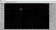
I bought a DATS V3 and used it to measure the speaker impedance curves of my cabinets. Below is an example. I know how to derive the low resonant frequency from this data (Fs = 105.2 Hz), but I don't know how to extract the information that would help me set the other speaker impedance curve parameters. Can any offer guidance on how to use the data to derive the Q and high frequency resonance parameters?

1710287081684.png
 
Tweak the Q until the low-frequency spike is shaped like the one in your plot. Q will make the spike narrower or wider.

Tweak HF Resonance until the slope on the right side of the curve best matches the slope on your plot.
 
Rex, thanks for the tips. I am hoping to get an explanation of how to use mathematical methods to determine the parameter values from the data.
 
Rex, thanks for the tips. I am hoping to get an explanation of how to use mathematical methods to determine the parameter values from the data.
The following is an approximation. The actual impedance curve of a speaker cabinet is a complex blend of impedances, and it's hard to unblend them to reverse-engineer what effect each parameter has. That's why it's easier to to tweak by eye as I described above.

Q is the center (resonant) frequency divided by the bandwidth. The bandwidth is the portion of the spike that's 3 dB down from the peak (which is half power). With a tube power amp, output power is proportional to impedance. So the half-power points for your 39-ohm peak will be 19.5 ohms. Look at your plot to see where on the curve the impedance is 19.5 ohms. Normally, there are only two such points. But because of a quirk in your cab's curve, that happens in four places. You have to choose which of the three to use in your calculation — another reason this can only be an approximation.

Anyway, subtract those two frequencies from each other. The result will be the bandwidth of the resonant peak. Use that information to calculate the Q.
 
Ok, dumb newb question. I’m using 2 Fender FR12’s. Should I worry about matching resonant frequencies of the cabs/speakers? Or is this mostly for actual guitar cabs?
 
Back
Top Bottom