How do impulse on/off convert to 1/0 numbers in computers?

RackAddict

Previous handle "Djenter"
I was wondering if somebody can answer me what on the surface may appear to be a very basic computer science question.
I have searched endlessly for what some think is an easy answer to this but I can assure you I have ended up at many dead ends trying to find this fundamental answer upon which all computer science lies, and that is, how exactly is it that an on or off impulse converts to a 1 or 0 that is then as binary math from that point forward (and yes we already do understand the binary part representing the on/off part. But what is the connected means? The channel?) How does an on impulse 'flick the switch' to a zero? And how does the off no impulse even 'flick' it if there is no impulse to do the flicking?

This point of conversion is what this YouTube series on computer science fails to explain. I have also looked into manuals and references at the computer science level and there was no answers.
I've even asked computer techs in computer shops, they dont know, and even computer science graduates seem baffled... even they don't know.
Yes, we know that an off is represented by a 0 and an on is represented by a 1. But what exactly is that representation at the level of the logic gate? Is there some sort of imprint that is connected on some sort of microscopic physical switch? How does the off 'switch to a 0 and the on switch to a 1? Is it like a mini injection mould at the atomic level that connects a no impulse to a 0 and an impulse to a 1? And how does that happen? Can somebody maybe make a sketch?
Because so far I haven't found any explanation that makes any sense.
And what about the other way around by means of the binary control? How does a 0 become no impulse and a 1 become an impulse? How does it know 'how' to react whatever it is? The 1 or the 0 - how do they become that? or the on or the off to the 1 or the zero.
 
Agreed sorry that’s a lot of reading/writing.

One thing that may help - there are no physical switches, but there are tiny transistors

So an AND gate is easily achieved you need current (=1) at both the input (the collector) and the switch (the base) if both are present it switches. If one is missing you won’t.

OR can be achieved using two ANDs (not sure if this is how they do it) where both the input values are presented to the switch (base) of the transistor

Hope that helps
 
It's not clear what your actual question is, but I'll take a stab at it.


If you're asking how 1's and 0's are used to compute stuff, then you'll have to study boolean logic, because that's how it's done.

If you're asking how boolean logic is implemented, the answer is logic gates. There are a handful of types of logic gates that are the building blocks of all digital computers.

If you're asking how 1's and 0's are represented electronically, that depends. It's usually done with solid-state electronic circuits that are driven outside the linear region (but there are exceptions to that). A circuit driven into saturation represents a one. A circuit in cutoff represents a zero.

If you're asking something else...???
 
Think of an arrow. The tip can point north, or south. The tip is magnetic. If there is an impulse, goes north, otherwise stay away from north (south).
The arrow could be some metal oxide (a bunch of), or a single atomic particle, or any device suitable to change state. There should be a way to write the info, and another way to read the info.

The representation at the level of the logic gate is a voltage (I think this is what you asked for). The physical device transform the "state" into "voltage", that is passed thru bus into other physical or logical device to be used.

As Greg suggests, there's a lot behind. Search books and courses, you'll find the complete answer!
 
The physical devise could be cardboard, a lamp and a opto (used in optocompressor... :cool:). If there's a hole, light pass, opto give some voltage, otherwise no voltage. The reader device has a range of voltage for logical on/off (1/0). To write the info, a puncture is done with electromagnetc device.
 
Look up binary representation and word size.

Yes, The computer works with ones and zeros but it commonly puts them in groups of 8 16 32 64 etc. to represent larger ranges of values. That may help you understand what's going on.
 
If I understand it correctly, you are asking how these binary states are stored in a computer. A historical approach may help to understand it.

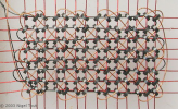
One upon a time, zeros and ones were stored at magnetic-core memories. It consisted of small toroid ferrites that could be magnetized through a current that circulates through at least a couple of wires, one to magnetize and another to demagnetize. The magnetical hysteresys allows to memorize the state. There you have a smart way to store Zeroes and Ones.

Answering the question at the OP title "How do impulse on/off convert to 1/0 numbers in computers?": a impulse through one of the wires would be converted to a 1 (ferrite magnetized), and a impulse through the second wire would be converted to a 0 (ferrite demagnetized)

The horizontal/vertical red grid is to write 0/1 at each individual core; the copper and black colored wires crossing all the cores are for a reset (write zero or one to all cores)
1652266101765.png

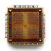
This is a 32 x 32 = 1024 bits (128 bytes) memory:
1652266022851.png
 
Last edited:
I think I understand your question. If I do, I have an answer.

The answer is basically rounding of continuous voltages taken at specific clock intervals.

For a normally-open FET, what happens is that the transistor connects a high-voltage (often ~3V) source to it's output when the input (gate) voltage is above a critical threshold. When the gate voltage is below that threshold, it disconnects the constant source from the output. A normally-closed FET does the opposite (high input voltage > open circuit on the output). Both are used in computer logic to build logic gates, which perform simple operations (typically NOT, NAND=not both, XOR = either but not both) that combine in different ways to do everything computers do.

So, the input to a transistor is a continuous voltage and the output is either an open circuit or a high voltage (minus some loss inherent to the stuff inside the transistor).

There aren't impulses, per se, except as these voltages interact with the clock for the device (which is basically a high-frequency square wave generated by a crystal oscillator), as the computer "measures" the output of transistors coincident with (usually, IIRC) the rising edge of that square wave.

The reason I say it's basically rounding is that the critical voltage for the gate isn't exactly "high" (whatever that is). Say it's a 3V high and you're talking about a normally-open FET. The critical voltage might be 1V. Which means that any voltage above 1V would turn into 3V at the output and any voltage below 1V would turn into an open circuit at the output. Each transistor essentially "rounds off" the actual value to high or open. The computer--in a big picture way--treats this rounding as quantization to 1 (high) or 0 (open).

But, yes, this is a computer engineering topic, not a computer science topic. Computer scientists don't generally care how transistors work. They also don't generally care that computers mostly use NAND gates....other layers of complexity hide the details....essentially because at a conceptual level, people work better with AND while computers are simpler with NAND (fewer transistors per gate), among a lot of other little details.
 
Thanks for all the answers.
trying to take it all in.

As for those who referred to logic gates and Boolean logic. I know what that is. I'm not worried about trying to understand those, I get the gist of it. The grid mesh arrow north/soouth explanation thing I think is helping me grasp this a bit more. But no cigar here. I really hope to see a video of a microscopic conversion of that state to number in action during the actual conversion! One at that video's microscopic state scaled up to viewable size.

I clearly do understand the state of the ferrites north on or south (not North) off explanation only as it pertains to what it represents. I just wish to know what is it at that exact point is that an imprint into a physical 1 or 0 before it's a digital version as the lit 1 or zero (which I already understand to be the abstracted version of that directional state).

I was just wondering if somebody can draw the mechanism of conversion or if there is some video evidence of this with some sort of video's microscope or nanoscope video.

Is it kind of like a calculator where the off state presses the 1 button and the off state presses the 0 button the way our fingers do only the 'finger's in this case being the 'compass arrow's tip? Is there any evidence of this in some sort of microscopic video blown up as evidence for us to see?

It seems unfathomable to think about the layers and levels.
And then I guess there would need to be sub layers that 'upholds' whatever amount of pixels that 1 or 0 now is in its mere 'lit' form. But it has to be some sort of thing pressing that impulse switch that's either north or south as Smilzo was referring to, and at the 'grid side' facing the back of what Ping has presented. Regardless of what combination of logic gates are happening, plus at the basic machine-lit state in whatever channel. But it must be trillions of sub-channels to get to the basic represented state. This is the part that's tough to wrap my head around.
 
Last edited:
There are no "impulses" in digital logic. Digital logic is all about "states". In binary digital logic a state is either 0 or 1 (off or on, false or true, etc.). Higher-order logic is also possible, i.e. tertiary which is three states per "cell".

States are stored using, typically, transistor-based logic. The basic unit of storage is the flip-flop. Modern computers use complementary metal oxide semiconductor (CMOS) logic which is based on n- and p-channel FETs.

In common binary logic states are manipulated using logic operators: AND, OR, NAND, NOR, XOR. A single bit, known as a boolean, can be used for program flow. Multiple bits can represent integers or floating-point numbers.

Mathematical operations are performed using arithmetic logic. Arithmetic logic uses the fundamental binary operators to perform calculations. For example, the OR operator, along with "carry" is used to implement addition.

Most computers use sequential logic, meaning they are clocked. At each tick of the clock states are retrieved and used as commands and data.

From here you get into the various computer architectures (Harvard vs. Von Neumann vs. Super-Harvard, etc.), memory architectures (DRAM vs SRAM), pipelines, etc., etc.

The next frontier is quantum computing in which states are superposed and entangled with the other states. It gives me thinky pain.
 
I really hope to see a video of a microscopic conversion of that state to number in action during the actual conversion! One at that video's microscopic state scaled up to viewable size.

I was just wondering if...there is some video evidence of this with some sort of video's microscope or nanoscope video.
There is no visible evidence of any of this. To understand why, imagine two wires passing in front of you. One of those wires is carrying enough electricity to kill you. The other wire isn't carrying any electricity at all. You can't tell which wire is which by looking at them.
 
I was wondering if somebody can answer me what on the surface may appear to be a very basic computer science question.
I have searched endlessly for what some think is an easy answer to this but I can assure you I have ended up at many dead ends trying to find this fundamental answer upon which all computer science lies, and that is, how exactly is it that an on or off impulse converts to a 1 or 0 that is then as binary math from that point forward (and yes we already do understand the binary part representing the on/off part. But what is the connected means? The channel?) How does an on impulse 'flick the switch' to a zero? And how does the off no impulse even 'flick' it if there is no impulse to do the flicking?

This point of conversion is what this YouTube series on computer science fails to explain. I have also looked into manuals and references at the computer science level and there was no answers.
I've even asked computer techs in computer shops, they dont know, and even computer science graduates seem baffled... even they don't know.
Yes, we know that an off is represented by a 0 and an on is represented by a 1. But what exactly is that representation at the level of the logic gate? Is there some sort of imprint that is connected on some sort of microscopic physical switch? How does the off 'switch to a 0 and the on switch to a 1? Is it like a mini injection mould at the atomic level that connects a no impulse to a 0 and an impulse to a 1? And how does that happen? Can somebody maybe make a sketch?
Because so far I haven't found any explanation that makes any sense.
And what about the other way around by means of the binary control? How does a 0 become no impulse and a 1 become an impulse? How does it know 'how' to react whatever it is? The 1 or the 0 - how do they become that? or the on or the off to the 1 or the zero.
At the switch gate level a comparitor is used to test an input voltage against a reference. A "low" signal (below threshold) is converted to zero voltage at the output, a 0. An above threshold voltage is converted to the reference voltage at the output, a 1.

In digital circuits, this is all coordinated by a clock signal - a regular 101010... pattern. All of the processors (comparitors, gates, alu, memory, etc) agree on when they will evaluate their inputs and generate their output (eg on a clock transition from 0->1, or on 1->0 transition). The devices hold their outputs for some specified amount of time (clock cycles). Internally, there can be various subdivisions of the clock to orchestrate the evaluate input-> generate output dance.
 
This thread reminds me of a CS/EE class in the 1970's on hardware design for low level logic circuits like adders or multiplexers. The lecturer was explaining the pin layout of a chip, the functions of all the signals of all the inputs/outputs of the chip and one of the, very few back then, gals in class asked "What's a ground?"

Seems like some of that's going on here: that logic states are represented by physical electrical or electromagnetic signals and these physical voltage/current/magnetic/light states are defined, depending on the circuit to represent the abstract (not physical) logic states.

exact point is that an imprint into a physical 1 or 0 before it's a digital version as the lit 1 or zero
There is never any 'conversion' from physical to digital, it's more like a translation. The physical is ALWAYS there and the digital version is the interpretation of how specific states (like voltage) REPRESENT the logical 1 or 0, like +5V is defined to be a logical 1 and 0V for 0. The physical state never goes away. There also can be some physical states that are in between, like from +2V to +3V that may or may not defined as a logical 0 or 1, depending on the circuit.

You might try checking out some articles or youtube vids on basic circuits and digital hardware design and it should make sense pretty quickly.
 
Last edited:
I guess there is lots of ways on/off has been stored, and then "queried" for computing, from early transistors to the tech being researched now (atomic...). Take 2 coins and position them to remember whether you need none, 1,2, or 3 new guitars (0=heads/heads, 1=heads/tails, 2=tails/heads, 3=tails/tails) - there, you've built a computer!. To me the fundamental of computing is the boolean counting (counting from 0 = 0,1,10,11,100,101,110,111,1000,1001,1010...). Everything stems from that. Take a course in assembler - will be quite useless practically, but enlightens one to the fundamentals which have become increasingly more distant / abstract to most involved, since computing began. I recall a prof assigning us to program long division in assembler (Z80 chip, something like that) - gave me extreme thinky pain - that type of coding not for me.
 
Last edited:
I was wondering if somebody can answer me what on the surface may appear to be a very basic computer science question.
I have searched endlessly for what some think is an easy answer to this but I can assure you I have ended up at many dead ends trying to find this fundamental answer upon which all computer science lies, and that is, how exactly is it that an on or off impulse converts to a 1 or 0 that is then as binary math from that point forward (and yes we already do understand the binary part representing the on/off part. But what is the connected means? The channel?) How does an on impulse 'flick the switch' to a zero? And how does the off no impulse even 'flick' it if there is no impulse to do the flicking?

This point of conversion is what this YouTube series on computer science fails to explain. I have also looked into manuals and references at the computer science level and there was no answers.
I've even asked computer techs in computer shops, they dont know, and even computer science graduates seem baffled... even they don't know.
Yes, we know that an off is represented by a 0 and an on is represented by a 1. But what exactly is that representation at the level of the logic gate? Is there some sort of imprint that is connected on some sort of microscopic physical switch? How does the off 'switch to a 0 and the on switch to a 1? Is it like a mini injection mould at the atomic level that connects a no impulse to a 0 and an impulse to a 1? And how does that happen? Can somebody maybe make a sketch?
Because so far I haven't found any explanation that makes any sense.
And what about the other way around by means of the binary control? How does a 0 become no impulse and a 1 become an impulse? How does it know 'how' to react whatever it is? The 1 or the 0 - how do they become that? or the on or the off to the 1 or the zero.
Look up analog to digital conversion process. There are bunch of videos on YT, but if you’re interested jump straight to the 2:50 mark to see an example in the video below.


As for “miniature switches”, like was mentioned already logic gates are made of transistors. Look up semiconductor device physics if you want to learn how a transistor is turned on or off (physically, as in electrons forming a channel in your substrate between source and drain). If you wish to go deeper, then learn about activation energy, energy band diagrams and eventually quantum mechanics (already mentioned).
 
Last edited:
k, I'll bite :D

common voltage level that represent the
  • 0's are 0V to 0.8V
  • 1's are 2V to 5V

The electronic circuits have some voltage level at an output.

If a 'transmitter' wants to send a 1, it puts (say) 2.3V on one of its output and that output goes to a 'receiver' through a wire, the receiver would be able to read that voltage (say) 2.2V (assuming some of the voltage was lost because of the length of the wire) on its input and will be able to interpret it as 1 since the voltage is between 2V and 5V.

Thus an analog signal (2.3V) is converted to a logical 1 by a receiver which is able to interpret the voltage at its input (2.2V).

Going further

0's and 1's are values.
A bit is a location of memory that can store either a 0 or a 1.
These bits are commonly grouped together in group of 8, 16, 32, 64, etc to store something else than an ON/OFF information.
When you group 8 of them together you get a Byte or a char, 16 would give you a 'short' or 'word', 32 would give you an 'int'(eger), 64 a 'double' and so on.

In order to send digital data from a transmitter through a wire (analog) to a receiver (back to digital again), you need an agreement between the sender and the receiver. That agreement is called a communication protocol. The protocol states the speed with witch data can be send/received, what a packet is comprised of, what are the rules when a packet is received or lost and so on.
 
Back
Top Bottom