Your point is well-taken. On my previous Temple Audio Duo 34 board, I did exactly what you did with a Fornstner bit, rasp and metal sandpaper to reduce the sharp edges. A Dremel would be ideal and would take the difficulty out of the entire drill process...
It's unfortunate that an IEC power cable does not fit thru an access hole, which requires some creative workaround thinking on owner's parts.
I agree that widening an access hole would work, IMHO, it just reveals the scope of Canadian design. I'm not faulting it, but just thought to offer an alternative in case
@Retired519's electrical wiring skills were better than his drilling ones.
I just thought that owning a Temple Audio board is quite a remarkable thing, so my feeling is that maintaining its integrity might be important to some.
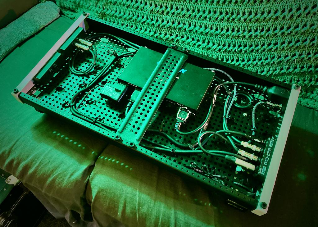
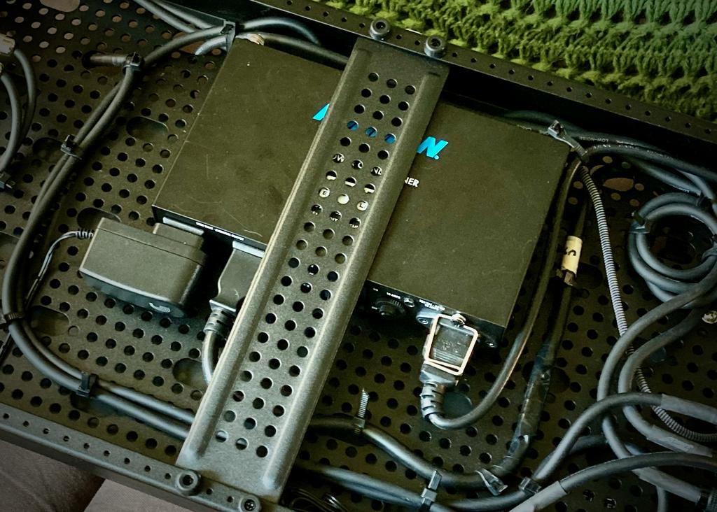
Yet, I'm curious. Do you happen to have an image of the underside of your Temple Audio board? Was wondering what your power connections were, and to what...EDIT: Ah, I see it, image 97041 from a previous post...good to see someone else using an AC215A...