Rex
Dignified but Approachable
I never set foot in that one. I had my fill of bad puns 30 years ago.The Dad Joke thread I had to step away from...
I never set foot in that one. I had my fill of bad puns 30 years ago.The Dad Joke thread I had to step away from...
The resistors are blue because that is the common color for precision 1% metal film.
I don't have a FR-12 yet.im buying one but dont own a Fco unit either.. yet..
We'll do our best to turn your thinking around.You know, I've always heard some bad things about "Fractal people" in some other forums, but my experience here in this thread has completely removed every ounce of unreasonable prejudice that I may have had before.


I am going to tag the Beta testers, except for Joe of courseI may have missed this in the thread but for the beta testers what was the general finding in terms of optimal settings. Obviously everyone's room and ears are different but the stock versions there was some common eq settings to make it more flat...
 he won't get his till Tuesday.
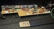
The layout is mostly aesthetic. But the EMI/EMF is way better, mostly from the grounding and the board orientation. I do use right angles to cross traces in routing the top and bottom layers, and use a really heavy buss for both V+ and V- on separate sides of the board, and there are zero! Vias in the routing... And I understand that magnetic fields propagate at right angles to the current, right hand rule, and basic design principles.Pretty as fuck.
Is the symmetrical component arrangement purely aesthetic or does it minimize noise/EMI?

Please tell me the blindfold isn't for the donkey.I use Sacred Geometry and Platonic Solids in my art and design, I am sure there is a benefit... but I could have improved on the stock design with a blindfold, some darts, and a donkey.
But Tevye... do you love it?every day when I check my mailbox I like to pretend the V2 is going to be there.
It’s probably a good time to admit a few things:
-I don’t understand 99% of what comes out of @WKSmith mouth
-I haven’t turned on the Fr10 since I stumbled upon this thread. I refuse to even look at it.
-the V2 project inspires me to be more conscious of the work I do. I tend to focus on path of least resistance and easier faster cheaper solutions, but seeing people going the extra mile to make better things (when even a half assed v2 would have been an improvement) is enlightening
- what am I going to do these OPamps from mouser? Anybody want them? I never attempted to install them
I appreciate all the work and obvious passion you’ve put into this project.The layout is mostly aesthetic. But the EMI/EMF is way better, mostly from the grounding and the board orientation. I do use right angles to cross traces in routing the top and bottom layers, and use a really heavy buss for both V+ and V- on separate sides of the board, and there are zero! Vias in the routing... And I understand that magnetic fields propagate at right angles to the current, right hand rule, and basic design principles.
There is a valid design point to be made though.. like the foil ends of capacitors orientation to the low impedance side, but this is a DC preamp, so it doesn't need as much AC protection like the HT tube amp circuits do.
I use Sacred Geometry and Platonic Solids in my art and design, I am sure there is a benefit... but I could have improved on the stock design with a blindfold, some darts, and a donkey.
Not at all. Those are resonant circuits that tune the filters. They are very low line level small signal devices.I appreciate all the work and obvious passion you’ve put into this project.
One question… I see that many of the components are in square clusters with the components seemingly right up against each. Are there any issues with heat dissipation?
Great, thanks for the explanation. Looking forward to getting the V2!Not at all. Those are resonant circuits that tune the filters. They are very low line level small signal devices.
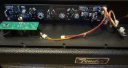
The only signigant heat is from the horn amp IC, and I used a much better heat sink than the stock preamp uses there.
