Fender FR-12 preamp mod : The Hissterectomy

some lovely graphs for the folks following all this.
I re-designed the first 2 stages and ran them in a simulator to see where tuning the phantom power protection leaves us.

I changed every.single.damn.value in the differential input side and cut its signal losses in half. So then I can also cut the makeup gain stage by half and keep the stage 2 output the same.

You may recall in my initial testing 600 posts ago, that the FR had major hiss in the eq and a small hiss in the front end. This tuning also kills the small hiss by cutting the gain in half ..and by lowering the circuits serial resistance (resistor noise) by 80-90%, still keeping the input impedance higher that the output impedance of the Fractal (and L6, and TMP, ..etc) for proper freq response.

The V2 tuning results in much better low end, and phase cohesion, and even more hiss reduction.

The charts have 2 signals in each graph. The top blue signal is post gain (2nd stage), the bottom orange signal is post differential amp (1st stage). The lower graphs are phase.


here is the stock FR

View attachment 132086


here is the V2 with phantom power protection.

View attachment 132087

and the V2 with one capacitor substituted becomes quite flat. This will be the V2 front end tuning and gain.

View attachment 132089
Please let us know when you test the real cab with your mod, to see if those simulations translate well to the real FR! I'm very excited to hear your impressions about it, specially if the so called "FR MOJO" was preserved after so many great improvements!
 
Please let us know when you test the real cab with your mod, to see if those simulations translate well to the real FR! I'm very excited to hear your impressions about it, specially if the so called "FR MOJO" was preserved after so many great improvements!

I will let you know quickly.
Instead of modding the stock FR front end again, I'm probably just going to measure and analyze the new boards. They are almost ready to order. I can always switch the values back.

That mojo is what I like best in the FR.
 
Not to derail this thread but one of the things I wish the FR had was two inputs. Is there a recommended way to add an additional input? They don’t have to be simultaneous. Just a simple switching ab box? I have not been able to find one that has XLR combo input.
 
Not to derail this thread but one of the things I wish the FR had was two inputs. Is there a recommended way to add an additional input? They don’t have to be simultaneous. Just a simple switching ab box? I have not been able to find one that has XLR combo input.
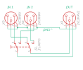
It would be pretty simple to use a DPDT switch for xlr pins 2&3
switching between 2 input jacks to one output jack.

It would be a simple project to put in a small enclosure. I am using the stock input and power supply / pass thru boards. Its not something that will be possible in the V2 Mod. But here is a schematic :D

xlr a:b.png
 
Last edited:
Wow that looks great! But probably beyond my abilities. I want to be able to connect my fm9 and the Kemper player (which I inadvertently bought - the continue button actually meant ”purchase” on the kemper web site) without pulling cables in and out. Pleasantly surprised by the the quality and clever design of the Kemper.
 
Humming Season 17 GIF by The Simpsons
 
Wow that looks great! But probably beyond my abilities. I want to be able to connect my fm9 and the Kemper player (which I inadvertently bought - the continue button actually meant ”purchase” on the kemper web site) without pulling cables in and out. Pleasantly surprised by the the quality and clever design of the Kemper.
Put the KPP in a loop of the FM9 and just run one cable to the FR (and have the ability to run a three amp rig lol).
 
Wow that looks great! But probably beyond my abilities. I want to be able to connect my fm9 and the Kemper player (which I inadvertently bought - the continue button actually meant ”purchase” on the kemper web site) without pulling cables in and out. Pleasantly surprised by the the quality and clever design of the Kemper.
Don't sell yourself short! This kind of build is exactly the kind of easy beginner project to get your feet wet with circuit building. Honestly, the hardest part about making this would be drilling the holes in the enclosure. There would be very few parts, no need for a circuit board at all, and no power. You could get a standard guitar pedal enclosure, three XLR jacks, one switch (either a DPDT toggle switch or use the standard DP3T pedal stomp switch and just don't use one of the three rows of lugs) and wire them up as shown above with only 8 pieces of wire.
 
Back
Top Bottom