DIY Axe-Fx Foot Controller for $50 (Open Project)

The issue was the Serial Speed. With the SY-1000 it can work at 57,600 without misses, but for the Axe-FX I had to set it at 9600 or it did not work at all (just the MIDI IN LED blinking)
weird that my other former suggestion did not work then (the standard midi serial port speed (31250bps) setting that I also suggested to change)
How can it not work at 31250 bps standard midi speed?
 
Hi all, If anybody is interested, BMC supports AXE FX 2, AX8 and Axe fx 3 syncing, BMC is only for teensy boards tho, also it has a Desktop editor where you can edit all functions (all stored in internal eeprom, i2c eeprom or sd card so no need to upload the sketch again), it supports buttons, leds, encoders, pots along with ili9341, ili9488, SSD1306 both 128x64 and 128x32 oleds and char displays all editable with the editor.

You can design a GUI and layout parts the way they are layout on your enclosure and it doesnt require you to write code for any of its functions unless u want to use the API to have custom functionality, with the config file maker you just need to assign what pins you wired your buttons, leds, pots etc and BMC will handle the rest, its open source and it also has logic control implemented for DAW control.

You can find BMC at badassmidi.com and the Arduino Library manager.
 

Attachments

  • IMG_4550.png
    IMG_4550.png
    393.7 KB · Views: 13
Even though this guy is doing a lot of stuff we already did (we did more complex floorboards I guess too) but the editor is certainly a great idea, very nice to see other guys crazy enough to build those things.
I built 3 generic midi controller boards with the PCB's I showed on this topic, but I think it is not for beginners (still lot of wiring is involved in my PCB's).
SO I'm currently thinking of building a zero-wire-needed pcb (not generic this time as my previous boards but easier to share with others).
 
You can build boards as complex as you want with BMC, assign events to press, release, hold, double press, release after press, release after hold and lots more plus you can use layers, on layer one you could control your axe fx 3 on layer 2 you can control logic, on layer 3 you can control both the axe fx and logic and so on.

Even with custom boards wiring is still the worst part unless you have large boards that will hold the displays and tactile switches with footswitch actuators but then you have to get them all lined up and make sure the distance between the actuators and the switches is right. I still usually end up with wires but instead i use JST wires as much as possible specially JST XH or SH and then make a custom board with sockets for them.
 

Attachments

  • IMG_4556.jpg
    IMG_4556.jpg
    808.1 KB · Views: 29
  • Screenshot 2023.png
    Screenshot 2023.png
    264.2 KB · Views: 28
  • IMG_7656.jpg
    IMG_7656.jpg
    1.7 MB · Views: 29
You can build boards as complex as you want with BMC, assign events to press, release, hold, double press, release after press, release after hold and lots more plus ../..
It's great indeed for those who can't easily design their PCB's for sure, personally I'm looking at something way more integrated (basically one larger board design).
 
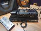
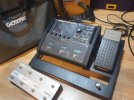
I've found a pedalboard GHOSTFIRE Standard 1.0 that can accommodate the FM3, one expression pedal, and there is room to install eight foot switches and the Arduino controller. It includes a cool transport bag, everything for $69.50

I will move the switches from the external enclosure to the pedalboard, so I will have everything in one compact board.

I will have to cover the bottom space with an aluminum plate because there is where I will install switches 7 & 8 (under the EV-5)
20231119_174739.jpg

20231119_174801.jpg
 
Very interested by any enclosure that could streamline quick prototyping, thanks.
For having repaired few pedalboards, I can tell they mostly all use the same tricks: there is no full switch inside, instead they use spring loaded triggers that push a simple SMD button soldered on the board and repeat that for as many buttons you need: that way zero wiring is needed between the board and the enclosure.

If we could use a standard form factor, I could design a board that fits it. Just a dream today though.
 
Last edited:
I post here the latest working version of the simple 8-scene controller, in case anyone wants to use it
C++:
// FM3 Scenes Contoller 28-Nov-2023 V2.3
#include <MIDI.h>
// https://github.com/FortySevenEffects/arduino_midi_library
#include <ezButton.h>
// https://arduinogetstarted.com/library/button/example/arduino-button-array

MIDI_CREATE_DEFAULT_INSTANCE();

const int BUTTON_1_PIN = 9; // define the pins where the switches are connected at the Arduino board
const int BUTTON_2_PIN = 8;
const int BUTTON_3_PIN = 7;
const int BUTTON_4_PIN = 6;
const int BUTTON_5_PIN = 5;
const int BUTTON_6_PIN = 4;
const int BUTTON_7_PIN = 3;
const int BUTTON_8_PIN = 2;
#define MIDICHAN 1  //MIDI channel
#define SceneCC 34  //CC for scene. Define the MIDI CC you want to send to the device

const int BUTTON_NUM = 8;  //***  total number of buttons

ezButton buttonArray[] = {
  ezButton(BUTTON_1_PIN),
  ezButton(BUTTON_2_PIN),
  ezButton(BUTTON_3_PIN),
  ezButton(BUTTON_4_PIN),
  ezButton(BUTTON_5_PIN),
  ezButton(BUTTON_6_PIN),
  ezButton(BUTTON_7_PIN),
  ezButton(BUTTON_8_PIN)
};

void setup() {
  Serial.begin(9600);
  MIDI.begin(1);

  for (byte i = 0; i < BUTTON_NUM; i++) {
    buttonArray[i].setDebounceTime(50);  // set debounce time to 50 milliseconds
  }
}

void loop() {
  for (byte i = 0; i < BUTTON_NUM; i++) {
    buttonArray[i].loop();  // MUST call the loop() function first
    if (buttonArray[i].isPressed()) {  // detect pressed button
      MIDI.sendControlChange(SceneCC, i, MIDICHAN);  // Send the MIDI data
      break;
    }
  }
}
 
Last edited:
Back
Top Bottom