Who understands what's going on here & wants to build this (for pay)? LED Rotary Rings

LAYGO

Experienced
I've been dreaming about a 1U (maybe 2U?) rack with just knobs & LED rings. I've worked with another member here who I paid for parts, etc to get some decent progress, but I think a lot of the motivation was lost with the introduction of the RAC12 + life. (I am by no means disparaging this other member). That project was all the way back in 2011-2012!

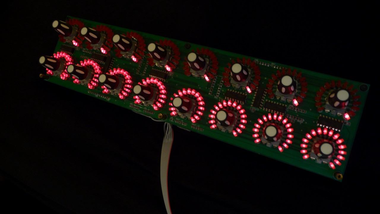
Well, I stumbled upon these videos earlier today & it got me all pumped again because it's like a perfect vision of what I wanted to get implemented. I believe an LCD screen is not necessary when the LED ring will give you an idea of what the value is. Do you really care if it's 4.76 vs 6.28? No, rotate until it sounds good to your ear. An LCD might be useful to give you an idea of what the knob you're rotating is for though.

Here is the discussion on group buys for the boards:
https://muffwiggler.com/forum/viewtopic.php?t=217920
http://midibox.org/forums/topic/21095-lre-4x1-breakable-rgb-led-ringrotary-encoder-pcb-bulk-order


Last edited:
Damn, this was back in 2012:
http://midibox.org/forums/topic/17378-control-surface-pcb-for-16-encodersledrings-bulk-order/
http://www.midibox.org/dokuwiki/doku.php?id=mb-lre8x2cs_pcb

http://www.ucapps.de/index.html?page=midibox_ng_manual_hw.html (scroll down to rotary encoders/led rings)

PCB8.jpg
 
Last edited:
OMG. I still have all those parts lying around in boxes (although I thought I returned the funds?). I've just decommissioned the controller that was using the 3 working LED ring pairs because I've moved to using neopixels which don't quite fit a 1U case but are fine in a floor based controller. In any case I had been thinking of plunking all those parts into the 1U rack case for kicks. Weird how this pops up at the same time.

Somewhat unrelated: on the weekend I made this up and sent it off for printing... these days I use Raspberry PI's to run controllers:
kxSf0lO.jpg


32 buttons, 4 analog in, 2 x NEO pixel bus... MIDI in/out.

I'll dig out what I have tonight when I get home and take a photo. I think it's potentially just plug and play with minimal work... It came out of a working system so all the code and PCB's already exist.
 
Last edited:
HEY FRET!! You & I are square. Make no qualms about that. I am on typing this from the PC I built on that case you helped me get shipped here! This will be my ride or die case! I LOVE IT!

I figured a RPi or Arduino probably is sufficient controller now. I'm am still excited about this & if you have some kit where I just buy my own parts, I am definitely interested.
 
Ok the promised pictures:


This is a generation after when you saw back in 2011. These are built specifically to fit in the 1U rack box pictured. There are some little issues with regards to how the light from the LEDs gets through the fascia, do I drill a hole for each LED? And the encoder knobs are a little short, only about 5mm sticks through the other side. Which doesn't leave a lot of room to stick a knob on it. Especially because the encoder is also a button. So you need some clearance.

The LED rings are RGB, but only 1 bit per channel. So there are only so many combinations of colour you can use.

The Raspberry PI pictured is a gen 1 board with a touch screen. Too large to fit in a 1U rack. The reason I decommissioned this system had nothing to do with the LED rings, but rather the screen wasn't reliable. It would flake out half the time when running SDL frame buffer apps. So I just bought a proper DSI touchscreen that works with a more modern and faster PI. Which of course needed a large enclosure. And there for a cascade of changes. Sigh.

The SPI breakout board next to the PI allows for multiple SPI slaves to be attached to the one I2C bus. Which is how I multiple multiple LED ring pairs onto the same circuit.

The most recent software is written to run on the PI but I reckon it could work on a lower spec micro, because the PI takes it's precious time to boot up. But sticking with the PI would be the lowest cost route in terms of engineering time. I would have to scavenge the MIDI circuit off something. I don't have a spare one of those, but I do have all the components as of today. I could build one easy enough or use a spare off the batch I sent to be printed on the weekend.

I guess what I'm saying is that with a reasonably small amount of work I could have this up and running. One further unknown is that all my code targets an AxeFX2... cause that's what I have. And while there is a little documentation on the AxeFX3 I don't have one to test with. I have some ideas on how I could possibly access one over the internet via VNC or TeamViewer but I'd have to have a development environment on the target machine that is connected to the AxeFX3 to check that the MIDI messaging works. Or someone local to Sydney where I could go to test...

Hmmm. I do want to get my own controller working first though. I've given myself January to get that done.
 
Have you seen this DIY board from Livid? I didn’t look into details too much, but it has plenty of connections for analog connections, LEDs, and MIDI I/O. It may be worth exploring.

The fact that it requires USB connections & has no actual MIDI ports makes it probably require a RasPi/Arduino interconnected. I want something that's plug/play like any other MIDI device/foot controller. That is speculation, because this isn't my expertise, just a semi-informed person with a significant want.
 
The fact that it requires USB connections & has no actual MIDI ports makes it probably require a RasPi/Arduino interconnected. I want something that's plug/play like any other MIDI device/foot controller. That is speculation, because this isn't my expertise, just a semi-informed person with a significant want.
Looks like the Brain v2 doesn’t require USB
It can also be operated without a USB host, using an optional 5V power supply.
 
There are some little issues with regards to how the light from the LEDs gets through the fascia, do I drill a hole for each LED?

On this video, you can see it's just a giant hole exposing all of the LEDs. Dunno how plausible that is?

I have no idea of what name of the type of cut surrounding the FC switches, small openings vs individual holes, maybe that's plausible?

This is all WELL out of my realm of capabilities.

This probably requires discussed tool(s) to make these cuts?
Screenshot_20200122-125108_PENUP.jpg
 
I was actually searching for the docs about Axe-FX MIDI controller integration when I found this thread. If anyone can point me to them I think I'd like to try making one of these part of my rig.
 
As I said I'd be finishing my main foot controller before starting any new work. So as an update to that, on Saturday I did actually finish enough to call it "beta" and on Sunday took it to a gig and tried it out live (playing bass tho, but I did use reverb, distortion and tremolo effects via the controller). The results were great except for one little itty bitty thing: the screen saver on the PI comes on after about 10 minutes. So I'll have to sort that out hahaha. And some layout / fonts could be bigger.

This is the 4th iteration of my pedal board, and uses a couple of new ideas that I haven't implemented before. The main one being potentiometer based knobs like this: https://photos.app.goo.gl/T9yDJj4VzEjs5goq6

They are "endless" pots that just go round and round like an encoder. So technically it feels like a normal pot, but behaves like an encoder. This is much more musical when adjusting parameters on the fly, and much higher resolution than an encoder. Now these pots are expensive... almost prohibitively so. I think I paid somewhere north of $20 each for them. Hence only having 2 instead 4 or more. If I track down cheaper options I might look at adding 2 more.

That said it's unrelated to the encoder based system I have left over from the gutted controller. Soz. Just sharing what I'm up to.
 
Last edited:
Back
Top Bottom