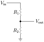
If you are handy with electronics you can just build a voltage divider in parallel to the speaker load to get a line level signal.
I saw a link from the Wiki page where Cliff had described the same type of Voltage Divider you suggest. I had posted there, but it's such an old post I don't think it's being monitored. Cliff's post was talking about ways to separate the Amp and Cab and the use of Load Boxes vs. Resistive Dividers
I cut and pasted the questions I had for this thread.
FractalAudio said:
Exactly!
The amps in V6 were matched this way. The speaker was not part of the equation. The benefit to this technique is that the cabinet is completely separated. "Profiling" lumps the speaker IR with the amplifier output IR since linear functions are not separable. That's why those products don't work well when you try to run into a power amp and conventional guitar cab.
You don't really want to use a load box though, if you can help it. A real speaker is a much more realistic load. All you need is a DI box that can handle speaker level signals. You don't even really need a DI box. All you need is a resistive divider to knock the voltage down to line level. I have a simple little box that just has some resistors and a pot to reduce the level which I then send to Input 2.
You seem to indicate that the Resistive Divider Box you use might work better than say the THD Hotplate, or other attenuator/load boxes. Could you shed some light on why this would be?
Also, does the Resistive Divider Box have to be able to handle the full speaker out load from the amp, or because it's a tap off the speaker and the speaker is left intact, is it less of a load on the box?
You mention a DI Box that can handle a speaker level signals, how does this differ from something like the THD Hotplate? Who makes a high quality DI Box that would function the way your Resistive Divider Box does?
The reason I ask is I'd like to build a box like yours, but have no idea how to go about it. I want to make sure I use resistors with a high enough rating that I won't burn them up or possibly damage the amp. Is there any way you could post a wiring diagram and picture of yours, or possibly a web link if it's available online?
I have the opportunity to match a friends great collection of amps, but I want to be sure I do it in a way that captures the tone the best way possible, and don't want to damage any of his amps in the process! Got all my money tied up in the Axe Fx 2, MFC, and RCF speaker etc, lol. Nothing left to cover any damages.

What method would I use to achieve results closest to what is used for the Factory Amp Models?
I was digging on the net and I came across this design:
Vintage Amps Bulletin Board • View topic - Dave's Inductive Dummy Load for Practice and Recordng
Any thoughts? Would this be worth trying, or be any better or worse than the THD Hotplate or the Resistive Divider Box you suggest? With real speakers instead of resistors for the load, would the amp react better than using fixed resistor values?
Sorry for all the newbie questions, but I'd love to end up with some really high quality Cab Ir's and Amp Match blocks that would be worth sharing with the forum, so any input would really be appreciated!
Thanks
Thanks