Figure 1
(a) Transverse bilayer metamaterial. The metamaterial is shown here in which the two colored regions are composed of regions with distinct acoustic properties placed transversely with respect to the wave propagation direction. (b) Acoustic transmittance through the transverse bilayer metamaterial for different values of acoustic impedance contrast (Z2/Z1) when the refractive indices ratio is kept constant (n2/n1=10). Notably, for the cases with a finite ratio between the regions' impedance (shown with the blue line, orange dashed line, and the yellow dotted line), Fano-like interference results in a destructive interference. However, in the case of infinite contrast between the regions' impedance, representing orificelike behavior, the destructive interference is suppressed (purple dotted dashed line). (c) Acoustic transmittance through the bilayer metamaterial for different ratios of the refractive indices when the acoustic impedance is kept constant (Z2/Z1=10). For different values of refractive index, destructive interference, i.e., attenuation, occurs where n2t=λ/2 and, consequently, silencing may be realized in the desired frequency regime by tuning the refractive indices.
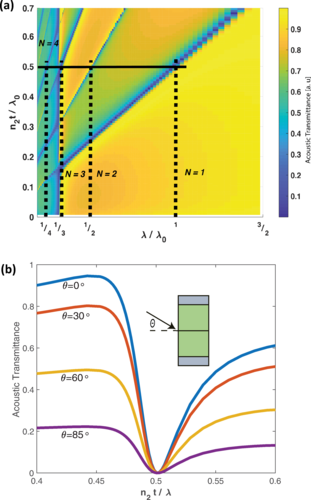
Figure 2
(a) Acoustic transmittance from transverse bilayer metamaterial structure with different refractive index ratios and a constant impedance ratio of ten. The silencing functionality initially emerges when n2t=λ/2 but is also present in higher-order harmonics when n2t=Nλ/2. (b) Acoustic transmittance through the transverse bilayer metamaterial in the case of oblique incidence with different incident angles.
Figure 3
(a) UOM structure is shown in which the open region at the center (r<r1) corresponds to region 1 in the transverse bilayer metamaterial and the outer region, featuring six channels coiled in the form of helix (r1<r<r2), corresponds to region 2. (b) Internal structure of the UOM is shown with an acoustic wave traveling through the channels and essentially following the helical pathway with a helix angle of ϕ. (c) Acoustic transmittance resulting from the impedance tube experiment is shown with the dotted-line with a triangular marker demonstrating that near 460 Hz, the transmittance is reduced to the minimum value of approximately 0.06. Sound transmission loss (STL) for the wave passing through the UOM is also shown with the dashed line corresponding the rightward y-axis. The solid line represents the predicted behavior using the Green's function method by modeling the UOM structure as a transverse bilayer metamaterial.
Figure 4
(a) The absolute pressure value normalized by the incident wave magnitude resulting from a plane wave with a frequency of 400 Hz and incident on the UOM from the left-hand side is shown using a color map. The local velocity stream is shown with the white lines. At this frequency, the transmission coefficient is about 0.85, hence, approximately 72% of the acoustic wave energy is transmitted. (b) The pressure and velocity profile is depicted with an incident plane wave of the same amplitude but a frequency of 460 Hz. At this frequency, due to Fano-like interference, the transmitted wave has a markedly decreased amplitude, and the wave has been silenced. In this case, the phase difference between the transmitted waves from the two regions of the metamaterial has resulted in a curvature of the wave velocity field and has diminished the far-field radiation. (c) Acoustic transmittance through UOM structures with different degrees of structure openness. Transmittance has been analytically derived using the Green's function method. Notably, UOM structures considered herein feature identical refractive index ratios in their transverse bilayer metamaterial model but have different impedance ratios.
")