MIDI Controller breakout board for accelerating new MIDI hardware designs

fab-gm

Inspired
As discussed in https://forum.fractalaudio.com/thre...r-50-open-project.119882/page-20#post-2295522

I'm currently working on a reusable PCB design:
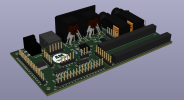
Rev. A will be equiped with :
  • 1 MIDI IN port
  • 1 MIDI OUT port
  • 1 USB 2.0 port
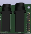
  • 2 Pedal for expression pedals (TRS) or simple passive switches for on off / sustain pedals use configurable with a jumper.
  • one demux for up to 16 switches (or 16 analog pots for other projects) controlled by only 5 pins
  • 2 x 8 leds shifters that can be driven with only 3 extra pins and all resistors already soldered
  • 1 external power barrel jack for optional MCU VIN
  • accepts both 3.3V and 5V logic (configurable with a jumper)
  • breadboard-like slots accepting a lot of MCU boards of different pin counts (breadboard like, for a fast connection to the attached periphals upper)
Other ideas / suggestions welcome !

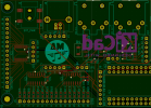
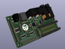
Here's a 3d rendering of my current PCB design:
MidiBreakoutFront.PNG
MidiBreakoutRear.PNG
 
Last edited:
Maybe a midi thru? And 4 exp / switch ports instead of 2? (can’t have enough of those)
OK, interesting: I thought about these and also about an extra merged midi IN to chain an existing midi controller pedal to our controller but there is a form factor impact doing those, but one can still use (and in fact even solder on the final prototype instead of using headers) those extra ports.

Now especially in case of the extra MIDI IN, it is IMHO a real value as it avoids you to implement an extra optocoupler circuitry.
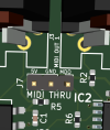
For MIDI thru one could reuse two of the extra optional HCT buffers I did not use yet and that I thought a header for these could be nice too (see picture on the right).

Now for pedals indeed, even with less space we could do something useful: what a pedal really is in the worst case (EXP) is just a GND/Vcc/Wiper(just an analog/digital from/to) connections, but right now it could be challenging because of the lack of 4 pin connectors,
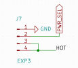
So I think I defintily can add 2.54mm 4-pins extra slots making trivial to add more pedals: these could be BTW direct Vcc/GND/Hot (from/to pins) 4 pins ?

What would be your use case for MIDI thru?

I just finished yesterday my first trace routing that could complete with 0 errors / warnings in terms of ERC but I can still add a bit there ...
1659709289809.png
 
Last edited:
@Reaper I am thinking of adding 2 extra 4 pin connectors for easy extra pedal installation like this (can be 3,3 or 5v logic all depending on the same jumper selection): note that the design below easily supports pedal switches too as one can just connect T and S ...

1659716136429.png1659718765482.png

EDIT: and here's a MIDI THRU optional connector:
1659727826112.png
 
Last edited:
well in hindsight, a midi thru for a foot controller isn't of much use, but perhaps for daisy chaining two footcontrollers?
 
well in hindsight, a midi thru for a foot controller isn't of much use, but perhaps for daisy chaining two footcontrollers?
OK I implemented both the midi thru and the extra pedals as optional extensions, as it probably won't hurt.

There was also a fairly new dual power supply super-integrated component out there, that I'd like to study and that already embeds a mosfet switch and much more that you would need to implement to get real dual power switching (USB and external power in our use cases) without causing the usual schottky diode based implementation voltage drop : the Fairchild FPF1320.
But the soldering of that puppy is quite challenging so I think we'll go old school and if we need this, just add a couple schottky diodes to our design. There is apparently a breakout board for this one if someone is interested by intelligent power switching.
 
Last edited:
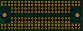
Here's the latest design (more breadboard-like surface under the MCU board for even more customization)
1659841325975.png
1659841521215.png
Tracks are connected by groups of 4 in the middle but the tracks can be easily cut to split them if needed, as it is easier to disconnect rather than connect them. This should allow for extra opto-couplers to add there with minimal soldering work for those wanting more out of this little board.
My recommendation for optocouplers is to use the fairchild H11L1(as cheap as H11L3 today so no need to use an H11L3 anymore IMO) because like the original PC900, it has schmitt trigger outputs and only has 6 pins to implement and gave me the best results over the 6N138 (btw if you want to use these darlington optos at least maybe use a 6N137 instead, I found 6N138 quite terrible to be honest and just enough to support the speed).
 
Last edited:
OK I implemented both the midi thru and the extra pedals as optional extensions, as it probably won't hurt.

There was also a fairly new dual power supply super-integrated component out there, that I'd like to study and that already embeds a mosfet switch and much more that you would need to implement to get real dual power switching (USB and external power in our use cases) without causing the usual schottky diode based implementation voltage drop : the Fairchild FPF1320.
But the soldering of that puppy is quite challenging so I think we'll go old school and if we need this, just add a couple schottky diodes to our design. There is apparently a breakout board for this one if someone is interested by intelligent power switching.
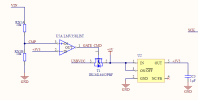
You could just copy the power auctioneering circuit that is used in Arduino boards, where an opamp (358) used as a comparator will turn on the P-channel MOSFET if the USB input voltage is higher than the DC barrel jack input voltage. It's a pretty robust circuit and doesn't need a hard-to-solder part.
 
There are already made mini breakout board already embedding a regulator if one needs additional care for this, but I think that most arduino or Pi boards you may use will have already what is needed, so I did not bother for this initial proto.
Which schematics are you referring to for the suggested mosfet power switching impl. using a 358 opamp ?
 
From the original UNO and several other boards, they use this circuit:
1660024509147.png
VIN comes through a Schottky diode from the barrel jack. If USB is plugged in, but VIN is higher enough, the U5A opamp keeps the P-MOSFET turned off (and it's body diode is probably reverse biased as well). If USB is plugged in but there's no DC jack, then the CMP input of the opamp is a 0V so the output pulls the gate of the P-FET to zero, thus turning it on harder (to overcome the drop across the body diode). So, when powered by USB you don't have voltage drop of a diode.

https://store-usa.arduino.cc/collections/boards/products/arduino-uno-rev3 on this product page (and others) they now have an interactive schematic/PCB browser - that's where I copied this screenshot from.
 
OK I see thanks, maybe it could be an option for a Rev B but at this time I'm thinking (at least when using Teensies and also Pi's if you'd like) there is enough on these boards so that we don't need to duplicate this functionality on this little extension board, at least for the first rev.
I plan to create more micro-breakout boards BTW, it could be a nice optional one to create so that we keep the floorboard design as modular as possible.

On Teensies BTW it's really simple: we can add just a couple of schottky diodes and reuse what's on their boards, see:
https://www.pjrc.com/teensy/external_power.html

@jordanyte, what system would you plan to use on a Pi? (the linux embedded image loads very slowly relatively to arduino embedded approaches). I think arduino boards have a much bigger OTS hardware library to reuse instantly?

Only used a pi to implement home network disk storage unit, and also did simple robotics with it to amuse my kids and I remember the GPIO's were actually quite slow compared to arduino pins. I would not use python interpreted code for this application but I'd be interested to learn more about it if it is worth the extra trouble.
 
Last edited:
OK finally received my first proto boards, only one stupid mistake only so far on Rev. A that I could correct fairly easily (bi-directional connections swapped on midi out).
Tested essential functionality before soldering more:
the cd4067 multiplexer and the 595 leds shifters all work great!
see below with my test buttons,did not test pedals yet except a continuity successful test but there is much less to test there so I'm pretty confident it's going to work.
If I could find the bigger (SOIC) version of the 4067 that would make my soldering experience so much easier, but I could still do it:
1661613572776.png

Some progress on the binder side too!
1661613880073.png
 
Last edited:
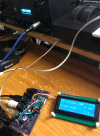
Yesterday new software version worked great first time i flashed it (features hi speed cmos handling of the 4067 custom driver when teensy's are used)!

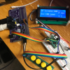
Now here's the fully assembled and tested concept board of this hybrid PCB General Purpose MIDI Controller with integrated breadboard slots idea I came up with...

Rev.B will reserve the 3 first rows for immediate teensy power and midi connections preconnections that will save 5 wires to connect or solder.
But right now even with all the jumper wires it's not too bad :) (simulating in Rev.A the use case of not having a teensy).

Here's a pic with some mess removed for the photo (but all functionality have been tested now!). I plugged a $10 Teensy LC to it and it rocks!

The board should support flawlessly all teensy + adafruit + arduino (like the micro and better) boards. So from the top of my head more than a dozen boards on the market already.

Also note that in this build, I built my own micro to USB B cable as I have all the parts but one can buy these for cheap pretty much everywhere, the cable will just be a bit longer.

1661831756595.png
 
Last edited:
Lots of improvements and new boards and software working really well so far, bug fixes in both the arduino controller board software and also the AxeFxControl library: Now updating the screen correctly when switch settings from the rack, not blocking when disconnecting cable in the middle of a sysex anymore,
Here are my github latest changes (only tested on various Teensy boards for now):

https://github.com/fab672000/AxeFx3FootController
https://github.com/fab672000/AxeFxControl

Note that I abandonned the SC_Button class use in favor of the latest standard Bounce2 Arduino button library. It seems that I don't have button click misses anymore.

Also cute modular new rev's and boards:
  • A simplified board i2c connection when using teensy's (direct onboard lcd i2c connection!), when not using teensy can be reused for other stuff too. Easier to solder footprint for the 4067 (could finally get stock on the SOIC version!)

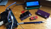
  • A MIDI in/out/thru card, probably the smallest midi for arduino card in the world accepting 3.3v or 5v with a jumper setting as it's bigger brother on the left :)
check the pic below, to assert and look athe small pcb relative to the pencil!
Also showing an off the shelf 4067 multiplexer for those who can't wait using 32-bit teensies of all models (no off the shelf solution for leds as in my bigger board though)!
1663530280488.jpeg
 
Last edited:
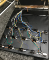
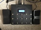
Some progress, here my newly assembled DIY foot controller baby!
1664060079720.jpeg
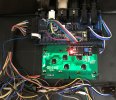
One board and one lcd is all the electronics connectivity inside... the rest are switch wires, still need to make room for leds, but not urgent:
1664060171829.jpeg
Still some work now on the software side but definitly glad about the first results!
 
Back
Top Bottom