How does this LM386 circuit boost bass?

hyuna

New Member
I'm just starting out in Electrical Engineering and was wondering if anyone could clarify a question about the following RC circuit regarding the LM386.

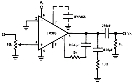
My question is about the following circuit:
eQMrG.gif

How has adding such a small value cap (between pins 1 and 5) in parallel to the internal resistor of the op-amp boosted the bass?

I have been reading the data sheet; under gain control it says the following:
Additional external components can be placed in parallel with the internal feedback resistors to tailor the gain and frequency response for individual applications. For example, we can compensate poor speaker bass response by frequency shaping the feedback path. This is done with a series RC from pin 1 to 5 (paralleling the internal 15 kΩ resistor). For 6 dB effective bass boost: R . 15 kΩ, the lowest value for good stable operation is R = 10 kΩ if pin 8 is open.
But I do not understand how it works, as far as I knew the bigger the cap the less capacitive resistance it has, so wouldn't a small cap (0.033 µf) as in the diagram be more resistive to bass frequencies? I know I have misunderstood something here.

All help appreciated.
 
I can't see the picture but my guess is it's modifying the q-factor of a high-pass filter (or supposedly some other kind of filter for that matter). A high q factor equates to a boost in a selected resonant frequency.
 
I'd guess the 0.033uF cap and 15k internal resistor make a high pass filter on the negative feedback loop of the amp. Cutoff frequency would be about 320 Hz, so amp gain would be higher for frequencies below causing the bass boost. Similar to presence and depth circuits in the negative feedback loop of tube amps. Filtering of the negative feedback loop allows you to control the amp gain relative to frequency.
 
I'd guess the 0.033uF cap and 15k internal resistor make a high pass filter on the negative feedback loop of the amp. Cutoff frequency would be about 320 Hz, so amp gain would be higher for frequencies below causing the bass boost. Similar to presence and depth circuits in the negative feedback loop of tube amps. Filtering of the negative feedback loop allows you to control the amp gain relative to frequency.
This is correct. Pins 1 and 5 are in parallel with the internal negative feedback loop of the op-amp. The capacitor shapes the frequency of the negative feedback.
But I do not understand how it works, as far as I knew the bigger the cap the less capacitive resistance it has, so wouldn't a small cap (0.033 µf) as in the diagram be more resistive to bass frequencies? I know I have misunderstood something here.
Since it's negative feedback, a high pass filter sends high frequencies back and subtracts them from the output. Subtracting highs is the same as adding lows (when gain matched), so you get a bass boost.
 
The RC network from pin 5 to pin 1 reduces gain at frequencies above the cutoff frequency of the network. The cutoff frequency is about 482 Hz. The gain will be reduced for frequencies above this (and slightly below since that's the -3 dB point).
 
The RC network from pin 5 to pin 1 reduces gain at frequencies above the cutoff frequency of the network. The cutoff frequency is about 482 Hz. The gain will be reduced for frequencies above this (and slightly below since that's the -3 dB point).

Hey Cliff, I didn't think you knew this sub-forum existed!

(less passive-agressively though, it's great that you keep sharing your knowledge here, it's much appreciated)
 
Back
Top Bottom