How Does One Wire an External Momentary Switch?

bleujazz3

Fractal Fanatic
Reason for my question is that I've viewed several YT videos that suggest toggle switches need wiring differently than momentary switches.

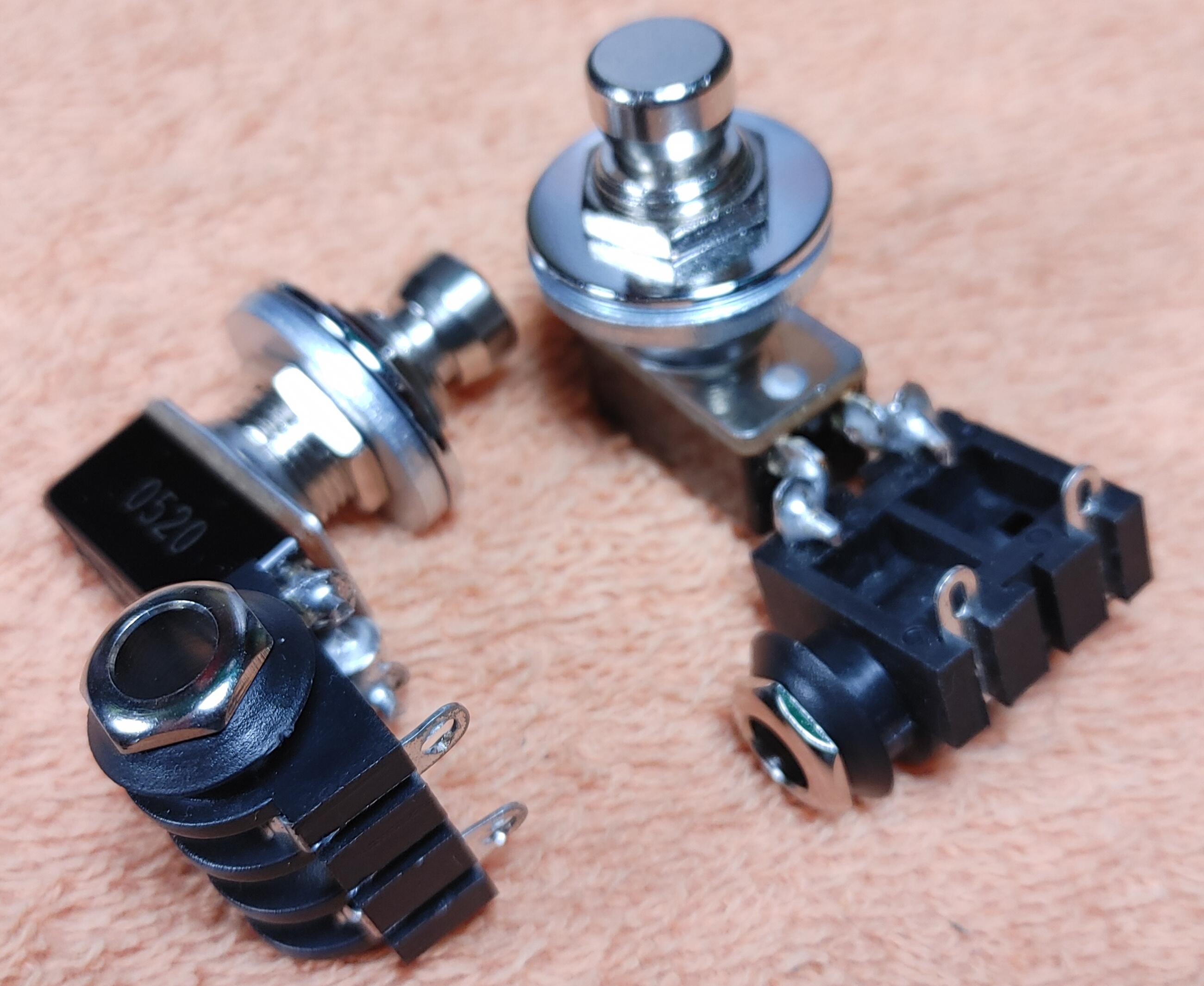
If using standard instrument TS cable, cut to length, outer insulation removed, braided shielding wire twisted, inner core insulation stripped, inner core wire trimmed, what's the best way to add a normally closed momentary switch? Based on what I've previously viewed on YT, the following is best practice:

My intuition tells me to simply place a large piece of shrink wrap tubing over the cable and set it far enough back so as to not interfere with the work. Then slide a piece of shrink tubing over each of the two wire strands, tin the soldering gun, tin the 2 switch lugs, and tine each strand of wire. Then, with a clean soldering gun and a little extra solder on the tip, solder each of the 2 wires to either tinned lug.

Then, once soldered, test the connection for continuity using a multimeter. Then, slide the 2 smaller shrink wraps over each wire towards the lugs, and heat the wrap tubing until it seals the soldered wire. Then, slide the larger piece of wrap tubing over the lugs, and use a heat gun to seal. Lastly, test for continuity once more.

If all checks out correctly, the switch is ready to install to the effects board.

For those who already know how to solder electronics, does this process sound correct to you? Since the switch is momentary and a TS instrument cable is used (opposite ends are right angle ¼" plugs), is it safe to say that the braided wire and core wire can be used to solder to the switch?

Thanks for your insight in advance. Having no prior electronics or soldering skills myself, thought your experience might be of value.
 
You can go through the hassle of shrink wrapping every end in there, but I never bother with it. These aren't carrying audio, so I'm not worried about keeping things isolated. There's no harm in it and really, if you get the shrink wrap on it nice and tight, it'll help secure the solder joints a little more, I suppose.

I made a little pictorial when I made mine, but I was making dual-switches. Still might find some stuff in there you'll find helpful, maybe not.
https://forum.fractalaudio.com/threads/diy-dual-momentary-switch-tutortial.158802/

Your steps are all great, you definitely think things through a lot more than I ever do. :tearsofjoy:
Actually, it's not possible for me to take credit for this. I just took notes when watching YT videos and made sure I didn't miss the important parts. Credit goes to the folks who do this kind of thing for a living and shared their experience.

Spending time with family and asking them to participate in the build was something of the sort that my Dad didn't do a lot of when I was younger. I guess when your old man didn't teach you how to change an oil filter, or tie a fishhook, or share a couple beers with you, you strive to remember to include family in your interests, otherwise those moments will be lost forever...:relaxed:

My hope is to do the soldering myself, but ask my younger brother, who lives in town, to visit and help supervise the switches installation. I think it might be wise to at least ask his advice and see if he'll lend a hand with the project.

EDIT: Dude, your thread was the inspiration for my build, though it was necessary with the FM9 to build flush-mount switches directly to my Temple Audio board! After seeing several additions examples of flush-mounted switches, the enclosure idea was scrapped because the FM9 requires 2-wire TS ¼" plugs. Am planning on putting the 2 switches to the far left on my Duo 34, to the left of my EV-1. (Am left-handed/footed, but play guitar righty, the reason for the switches/expression pedals location)
 
Last edited:
Here's my updated switches that I set up for the FM9:
IMG_20210928_215358.jpg


I used a couple pieces of 14ga solid copper from a piece of Romex wire to connect the jack and switch, along with some 60/40 solder. The jacks are pretty solid mounted this way. A regular Cliff style jack with solder lugs will work. I had the fancy ones with the chrome nut around in a drawer, so I used those.... :)
 
Another thing to consider is the Solder type, size and wattage iron! Small gauge wire does not require a lot of heat to get the job done! Shrink wrapping is a nice touch to your work and does help in preventing potential shorts or in some cases keeps wires from breaking and just looks sano!

Keeping the tip clean on the iron is a good idea as well! Dirty tips make for bad solder joints. Have a wet sponge handy to clean the tip when it starts to get resin build up. A quick wipe of the tip on the sponge will do.
 
Here's my updated switches that I set up for the FM9:
IMG_20210928_215358.jpg


I used a couple pieces of 14ga solid copper from a piece of Romex wire to connect the jack and switch, along with some 60/40 solder. The jacks are pretty solid mounted this way. A regular Cliff style jack with solder lugs will work. I had the fancy ones with the chrome nut around in a drawer, so I used those.... :)
Actually, the jacks won't be necessary...the switches will connect via TS instrument cable under the Duo 34 and via ¼" TS plug to the FM9. No drilling of Duo 34 board required, just some cable zip ties.
Another thing to consider is the Solder type, size and wattage iron! Small gauge wire does not require a lot of heat to get the job done! Shrink wrapping is a nice touch to your work and does help in preventing potential shorts or in some cases keeps wires from breaking and just looks sano!

Keeping the tip clean on the iron is a good idea as well! Dirty tips make for bad solder joints. Have a wet sponge handy to clean the tip when it starts to get resin build up. A quick wipe of the tip on the sponge will do.
Some good advice here. Purchased some extra 0.6 mm lead-free solder, and am using a 60W soldering iron. The reason for the lower wattage is because the solder only needs to heat to 360°F to flow correctly.

Viewing YT vids, each vid was mostly pretty descriptive stating about tinning each surface (iron, wire, lugs), and being sure the iron is tinned and clean. Have not peeked inside the soldering kit yet, will do so after lunch.

Also purchased a decent multimeter for checking continuity. Not sure how to go about this...once the soldering is complete, do I check across tip/sleeve of the ¼" plug? Or somewhere else? What Ω (ohm) value should I look for?
 
Also purchased a decent multimeter for checking continuity. Not sure how to go about this...once the soldering is complete, do I check across tip/sleeve of the ¼" plug? Or somewhere else? What Ω (ohm) value should I look for?

Yes, connect test leads to sleeve and tip.

Meter should switch between open (infinite ohms) and closed (0 ohms, approximately) when the button is pushed.
 
Actually, the jacks won't be necessary...the switches will connect via TS instrument cable under the Duo 34 and via ¼" TS plug to the FM9. No drilling of Duo 34 board required, just some cable zip ties.

Some good advice here. Purchased some extra 0.6 mm lead-free solder, and am using a 60W soldering iron. The reason for the lower wattage is because the solder only needs to heat to 360°F to flow correctly.

Viewing YT vids, each vid was mostly pretty descriptive stating about tinning each surface (iron, wire, lugs), and being sure the iron is tinned and clean. Have not peeked inside the soldering kit yet, will do so after lunch.

Also purchased a decent multimeter for checking continuity. Not sure how to go about this...once the soldering is complete, do I check across tip/sleeve of the ¼" plug? Or somewhere else? What Ω (ohm) value should I look for?
There should also be an audible tone that lets you know you have continuity! Measurements although not that important should be in the .2-.6 range depending. If you have anything in the 1.0 or higher you may have a cold joint.
 
Hmm. Will need to check continuity again. Each cable read 0.L Ω? I'm not sure my multimeter has an audible tone (will need to check). Soldering was as expected, a good college first try. Although one of each wire disconnected from the lugs once the switches were installed, a quick repair and securing with zip ties has things holding together nicely. Here's the finished product...

J1p22LR.jpg


AYwK3vH.jpg


K9ik5tw.jpg


EDIT: Just rechecked continuity (heard the tone this time). The resistance varied greatly (numbers jumped from 0.01 to 0.34) with switch closed. This is for the setting for 0.L. Looks good to you?
 
Last edited:
Hmm. Will need to check continuity again. Each cable read 0.L Ω? I'm not sure my multimeter has an audible tone (will need to check). Soldering was as expected, a good college first try. Although one of each wire disconnected from the lugs once the switches were installed, a quick repair and securing with zip ties has things holding together nicely. Here's the finished product...

J1p22LR.jpg


AYwK3vH.jpg


K9ik5tw.jpg
Normally open switches? Those should read open circuit until pushed, and at or near 0 ohms when pressed.

Build looks clean....
 
Normally open switches? Those should read open circuit until pushed, and at or near 0 ohms when pressed.

Build looks clean....
Normally closed switches. Because of fumble fingers, not possible to hold multimeter leads and press switch at the same time...bubble gum and walking wasn't my strong point in school...will ask family to visit and lend a hand in this...just for my reassurance, will need to know what happens when the switch is pressed open.

The build looks clean now...you shoulda seen me trying to repair the loose wire erstwhile swearing a blue streak cuz the darn thing loosened up when the switch rotated in its socket until it tightened in...
 
Last edited:
Family just stopped in for the multimeter test. When pressed (hold) the circuit read 0.L Ω.

These are the correct momentary switches (normally closed)? Tell me I didn't screw up...:oops:
 
Fractal gear can use either normally open or normally closed switches. That's what the polarity setting is for.

If you're getting the same reading when pressing the switch, you've either got a short somewhere or the switch is bad. Make sure there's no solder bridge between the two switch lugs.
 
Fractal gear can use either normally open or normally closed switches. That's what the polarity setting is for.

If you're getting the same reading when pressing the switch, you've either got a short somewhere or the switch is bad. Make sure there's no solder bridge between the two switch lugs.
Phew. Just RTFM pg 12, 79, & 94. Pg. 79 speaks about Stand-In switches, which is what these 2 switches will be used for. Pg. 12 addresses External Switches, and Pg 94, Switch Polarity.

When the switch is pressed and held (it's normally closed when not pressed), the reading is 0. That would be consistent with a momentary break for a normally closed switch, yes? The reading varies between 0.02 and 0.4, for when the switch is pressed and released, or pressed and released again.
 
Last edited:
Depends on the meter. An open circuit is infinite ohms. A dead short is zero ohms. Different meters will show an open circuit in different ways. Touch the two test probes together and see what is says compared to when they are not touching. Also, on many multimeters, you need to have the test leads in the right sockets on the meter. There's often one set of jacks for current measurement and another set of jacks for everything else.
 
Depends on the meter. An open circuit is infinite ohms. A dead short is zero ohms. Different meters will show an open circuit in different ways. Touch the two test probes together and see what is says compared to when they are not touching. Also, on many multimeters, you need to have the test leads in the right sockets on the meter. There's often one set of jacks for current measurement and another set of jacks for everything else.
It's likely the meter. It's an AstroAI. Touching the 2 leads together (correct sockets) produces produces a jump until it settles in about 000.1. I'd guess that the switches have at least that either way. 0.01 to 0.34, but 0 when the circuit is pressed down and held in momentary break.
 
Yeah that sounds about right. The wire in the instrument cable has a tiny bit of resistance, so when the switch is closed you should be getting the very small resistance. My Radio Shack meter shows OF for an open circuit. I bet the OL is the way yours shows it.
 
It's likely the meter. It's an AstroAI. Touching the 2 leads together (correct sockets) produces produces a jump until it settles in about 000.1. I'd guess that the switches have at least that either way. 0.01 to 0.34, but 0 when the circuit is pressed down and held in momentary break.
Most meters have a "continuity mode" where they beep when there's continuity between the two test points. Use that. Easier. Just listen for beep/no-beep.
 
Yeah looks like on the AstroAI, it's on the same dial setting as resistance, capacitance, and diode check. You hit the select button to change between them. The symbol is a dot with little waves coming off of it sort of like on my avatar.

This one:
dalkovy-ovladac-pro-infrazaric-veito.png
 
Most meters have a "continuity mode" where they beep when there's continuity between the two test points. Use that. Easier. Just listen for beep/no-beep.
Yup. Just needed to re-RTFM. LOL.
Yeah looks like on the AstroAI, it's on the same dial setting as resistance, capacitance, and diode check. You hit the select button to change between them. The symbol is a dot with little waves coming off of it sort of like on my avatar.

This one:
dalkovy-ovladac-pro-infrazaric-veito.png
Thx. The instruction manual font is very small, but could read on the device the screen posted above. Likewise, one selects Ω on the function wheel, then presses 'Select' until the radar screen comes up. If the connection has less than 30Ω on it, the continuity beep sounds continuously. I think I need to move onto Volume 2 of this course...thanks for your help. Connections look good, and more importantly, are viable.
 
Back
Top Bottom