FCB1010 Re-house project

Dutch said:
Great project BTW!!!

I've been thinking of cutting mine in two, seperating the pedals from the buttons and reattach with hinges to fold them back. That would make the pedal much easier to transport.

Well, the power supply is mounted on the pedal side of the FCB, if you didn't do phantom power it could be problematic.

But this discovery about a pot working too opens up possibilities.

Pretty easy to make your own expression pedal BTW.
Usually they use 10K linear pots. Get one of those cheap wah's from China (like $25) rip out the guts and put that pot in. If you want to go perfect get a momentary switch and you can do the total wah thing. Total cost about $30.
I don't know if Mission does anything extra except spray paint and assembly, which is costly, BTW... But I am sure that this would work.

I've already made one from an old Crybaby, it has a 100K pot that works ok. If you price the cost of a quality wah shell and the internal components, the Mission pedal is a great value. If I didn't already have this one I'd get theirs. I may end up ordering the pot from them. Standard pots won't work well in these type pedals, because of their limited travel.

I already had the latching switch, it will go into expression pedal 2 input - I may have to add a resistor for this, so that it toggles between two values and I can use it as an IA. I may add an LED to the wah/expression pedal itself for this switch. The FCB pedal LED's won't do anything for this, I chose to leave them off because it only shows if the the expression pedals are enabled in the patch - and they're always on in every patch. The latching switch I used is a 3PDT, so I can use one set of contacts for an LED and tap into the 5V from the FCB's expression inputs. If I used it for Wah only I wouldn't bother, but I'll be using it for various functions in different patches so it will be good to know when it's enabled.
 
Finally, getting the enclosure cut by CNC, hopefully will have it done this week.

I've been thinking about setting this up with 4 presets and 6 IA's. It would be a bit of a workaround, basically I'd use switch 10 as tap tempo and switch 5 as tuner. But I'd flip them so that switch 10 is on the bottom row and switch 5 is on the top. I'll have to program switch 5 to the CC of the tuner. I don't like having tuner on the bottom row as it's too likely to engage accidentally. I also don't like having tap tempo on the second row, have to stand on one leg while tapping.
 
Well, it's been awhile getting the enclosure but worth the wait :D . I was fortunate to get a favor from someone in the industry, and they made this for me out of mirror stainless steel - I'd just asked for sheet metal, planned to paint it but I don't know now....maybe I'll just hand paint the lettering and call it the "Vexter FCB1010" lol

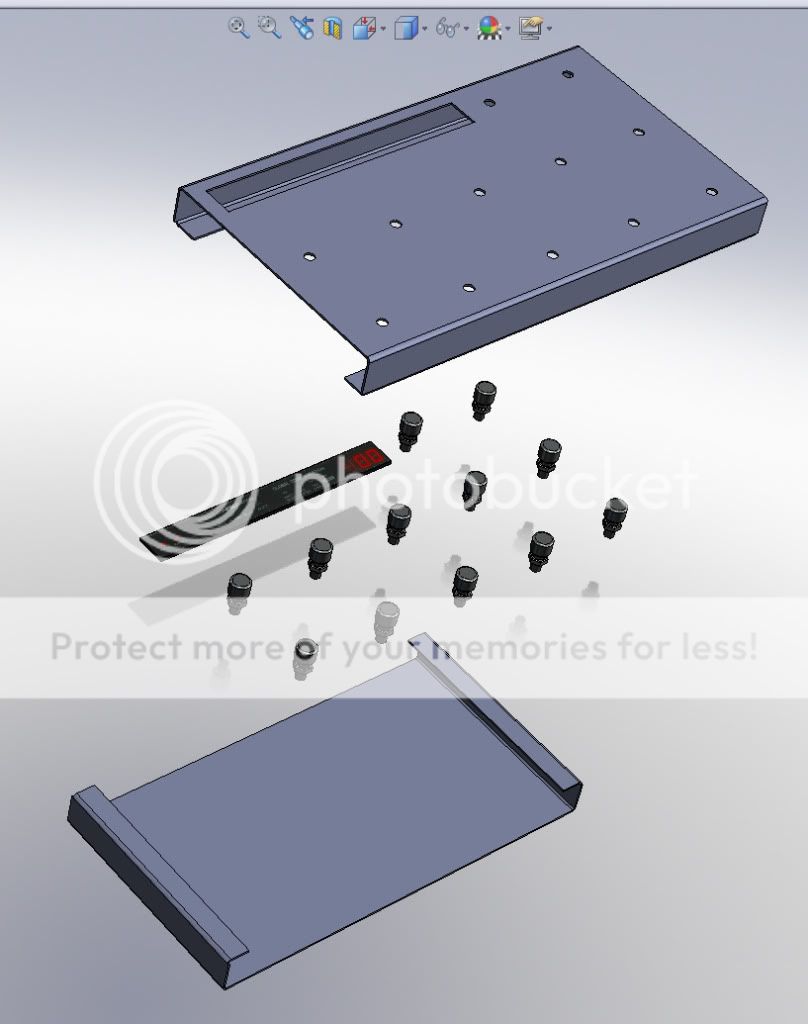
Big thanks to forum member guitarded for drawing this up for me.

mc1a.jpg

mc1b.jpg

mc1-fcb.jpg
 
Testing the fit of the display panel, switches, and LED bezels.
mc1c.jpg


Showing the detail of the construction, looks like a commercial kitchen counter lol .... I think I'm not going to paint or put any lettering on it.

mc1d.jpg
 
this is insanely frigging awesome!!

If I understand correctly, you wil wire a jack to the wires going to the pedals now, so you can plug in any 'volume type' pedal, which will generate the CC now generated by the pedals? Yes?

(Sorry, I'm not technically inclined)
 
hole said:
this is insanely frigging awesome!!

If I understand correctly, you wil wire a jack to the wires going to the pedals now, so you can plug in any 'volume type' pedal, which will generate the CC now generated by the pedals? Yes?

(Sorry, I'm not technically inclined)

Well, some volume pedals can be wired as expression pedals, but dedicated units have a 3 conductor "TRS" for single cable connection. The CC is generated by the chip, all of the "brains" are on the circuit board which is underneath the display and the same approximate size. The built-in expression pedals are connected internally with 3 wires, one of these carries a 5V "control voltage" - you can see old analog units with "CV" inputs and expression pedals work the same way. So basically it's going from 0V to 5V, which is translated to 0 - 127 by the FCB brain. It's pedals each have a small board underneath with additional circuitry for the optical photo resistor, but it's not necessary for a standard expression pedal.

So this will have EXP 1 and EXP 2 inputs. My intention is to use only 1 pedal with a switch which plugs in separately to the second input - same concept as the Mission Pedal. I may have to add a resistor on the switch so that it will toggle between two values, that's the only portion I haven't tested yet. Unlike the AxeFX, the FCB has no setting for "momentary" or "latching" pedals. It's "brain" will think it's an expression pedal. But for purposes of bypassing FX blocks, all it needs is two values.
 
Got the switches & LED bezels mounted, nothing hooked up inside but I stuck a watch battery in a couple of LED's to get an idea of how it will look.


mc1e.jpg


mc1f.jpg


And one with my foot for reference

mc1g.jpg
 
Truly one sick thing you have there. Case like that must cost more than an FCB1010. Or two. Very nice job on the side joints.

I'm keeping an eye on this! Love the size of it too.
 
Dunno how 2 FCB's would work as each would have it's own display/'brain'.

BUT, I am interested in this if the cost of the case + leds + switches isn't overkill. tubetonez, dare I ask how much all that cost? I could mod one of my FCB's when I need a smaller footprint is my idea.

Looks about the size of a LFjr.
 
LAYGO said:
Dunno how 2 FCB's would work as each would have it's own display/'brain'.

BUT, I am interested in this if the cost of the case + leds + switches isn't overkill. tubetonez, dare I ask how much all that cost? I could mod one of my FCB's when I need a smaller footprint is my idea.

Looks about the size of a LFjr.

The switches, LED's, and jacks were around $80 shipped. Like Dutch mentioned, it would be prohibitively expensive to get a SS enclosure, I lucked out on this. I will inquire if they can build it with sheet metal and a simpler assembly, no welding - like guitardad's drawing:
Untitled-2-5.jpg
 
A little progress, hopefully in the home stretch now. I decided to mount the power supply internally in the AxeFX:
mc1h.jpg


Finally got all the misc holes drilled, man that SS is some tough stuff. Here it is ready to wire & solder:
mc1i.jpg


And a little over half way done wiring:
mc1j.jpg
 
Back
Top Bottom