DIY MIDI to RJ45 <--> RJ45 to MIDI without soldering

Axelman8

Experienced
20210607_144051.jpg

Hey there,

If you are controlling your Fractal unit with MIDI but your running out of cable length or you want to use 1 single cable for MIDI in / out and perhaps power, than you can easily run them over RJ45 CAT5 or CAT6 cables. This solution is even without soldering.

In my case, i connect my peddle board with MIDI and USB power to the Axe-Fx III and just recently replaced the 3 cables with one 10 meter CAT 5 cable solution.
How long the maximum length of the RJ45 cable can be with MIDI signals I don't know, but with 10 meters I cannot detect any difference in productivity or power-loss on my peddle-board.
I use USB power for my peddle board, but I Guess you could use any 3V,5V, 9V power over the CAT5 line (i did not test 5V and 9V, but theoretically it could/should be possible)

How to do it:
I got the idea from several sources, but this video gave me the best insight information how to re-use standard soldered MIDI cables: Vertex Mod custom MIDI cables
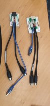
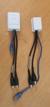
  • I bought two RJ45 wall connection CAT6 cases that have a non-solder solution. (one case is bigger than the other, i did it just for testing no particular reason)
  • Use 2 standard MIDI cable (I had just 1 cable, so i split it and did solder 2 connections) But for the non solder option, you need 2 cables and cut them.
  • I marked the outside of my cable with some tape, so i know which is which.

midi.gif
In my case this is the front view looking at the pins

Connections:
  • MIDI in my case uses 3 pins: Ground =2, VCC =5 and Data =4. (if you have phantom power, you could use pins 1 and 3)
  • USB for power uses 2 wires: Ground and VCC ( in my case black is ground).

Just insert the cables in the sockets, close it up and your done.
20210607_114016.jpg

There are similar possibilities like here, but i preferred a closed case:
http://www.carnationconstruction.com/Techniques/08-01-Techniques-AutomationAndData-DataWiring.html

NOTE:
The CAT6 RJ45 wall mount can be bought anywhere, only my version has a closing grid that holds the patched cables in place: For instance the "Ali" versions don't have this option. These cases are around 6 Euro's each with a closing grid.

20210607_105237.jpg


Cheers
 

Attachments

  • 20210607_114016.jpg
    20210607_114016.jpg
    1 MB · Views: 29
  • 20210607_144051.jpg
    20210607_144051.jpg
    1 MB · Views: 19
Power over the CAT 5 shouldn't be a problem. PoE (Power Over Ethernet) used in networks provides something like 12 Watts at 48 Volts DC to connected devices, so the cable can definitely handle it.
 
Power over the CAT 5 shouldn't be a problem. PoE (Power Over Ethernet) used in networks provides something like 12 Watts at 48 Volts DC to connected devices, so the cable can definitely handle it.
Thanks for the reply.

I had to rethink the usb though, the 15 tft on my peddleboard were not shining as bright like with a normal usb cable connection. It is working, but i need the screens to be bright.

I use a 5 volt powered USB hub to power the pedalboard, but somehow the current is weakened over the cat5.
Still trying to figgure out the right connection. It is 2 cables, but perhaps the single copper line that is in the usb cable has some function too.

Just cut my second usb cable . I Am working on it now. Your reply gives me the insurance that i will get it to work properly.

Cheers
 
Probably the voltage drop through the cable pulling down your 5V power rail. How much current are you drawing for USB power?
 
Probably the voltage drop through the cable pulling down your 5V power rail. How much current are you drawing for USB power?
Hey there,

It is an Arduino due that I am powering with the USB. It has a broker on board that decides what current to output for a connection (3.3 or 5V). Physically the screens are connected to the 3.3V. The arduino input is taking 3.3 Volts but can deliver 5V output.

I guess i have to adjust my USB connection. It is a USB A<-->B cable with 4 carriers and 1 copper line. Still trying to find the solution, tonight i did not succeed. The black and red wires are working though, thought maby the copper wire is ground also, but it made no diffrence. Will see tomorrow if i can make some progression.

Cheers
 
Hey there,

I did some reading and think the copper wire has to be used with the ground connection:

"
Extra bare wire within the insulation
That is the drain wire that helps carry charge off of the foil jacket and carries more current than the foil can.
It is part of the shield/ground of the cable.
"

I will cut a new cable tonight and try again (good thing they come cheap)


Cheers
 
Back
Top Bottom