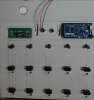
Bunch them up. All grounds are equal, so you can put multiple wires on a single pin or spread them out across several ground pins in groups. You can even run a wire from terminal to terminal and then from the final terminal go to a ground pin on the Arduino. If you look at the top of
@Piing's picture above, that's exactly what he did with the white wire that goes from switch to switch. It's a daisy chain to ground. He even tied ground on the LEDs by the switches to that run it looks like.
Use a consistent colour wire for ground to make your life easier when you troubleshoot.
")
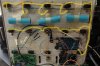
Regarding our solder picture, double check you didn't short anything out there? Use a continuity checker on your multimeter to test that there's no connection between each pin. Touch a probe to one pin and then the other probe to another pin -- if it beeps, you've got a short. Repeat test for all combinations of pins. It's hard to tell from your picture, but I'd definitely check that for shorts before I connected it to my Arduino.