DIY Arduino Foot Controller

Grit

Member
Well I've been working on this little gizmo for the past few weeks, finished it today and thought some of you guys might enjoy a look...

I wasn't quite satisfied with the FCB1010, because the expression pedals were flimsy, the buttons were chunky and too close together, and I needed some more external switch inputs in order to give my co-guitarist some controls for his own effects (in my band we put both guitarists through the Axe). Could have bought an MFC, but personally I think it's a bit too big for what I need, and also fairly expensive... total cost for this (not including time spent building it) was not far off £100.

At risk of sounding like a salesman, easiest way of giving a quick overview seems to be to list the features:

Current Features
  • Six heavy duty, silent footswitch buttons
  • Sends PC and CC messages - top LEDs (red) display current preset; lower LEDs (blue) display stomp-box style fx states (I don't use scenes due to having two different people pressing buttons)
  • Receives Tuner Sysex to show on red LEDs while tuning (so you don't have to look at the Axe's screen)
  • Three expression pedal inputs (with individual calibration)
  • Two external switch inputs - can use two mono jacks or one stereo jack. Dedicated, hardwired LEDs show the status of the external switches on the main board
  • CC channels for the expression pedals can be changed using the buttons - something also possible on the FCB but otherwise quite unusual, I think
  • Rock-solid aluminium casing
  • Reprogramamble Arduino Micro functions as the "brain"
  • Can switch between different modes of operation (seeing as it'll do whatever the code tells it to do)
  • Battery Powered
  • Tool-less dis-assembly for reprogramming or battery change
  • Easily fits inside a rack case for transport with the Axe
  • Protection circuitry shields the Arduino from any static shocks etc that might come in through the inputs (...hopefully)

Future Features
  • Need to figure out the best way to neatly label all the inputs, outputs and switches
  • Could be very easily programmed to use scenes, or send Sysex messages to the Axe (to control things like amp bass/mid/treble etc that can't be controlled with CC messages)
  • Include ability to power the unit through the midi cable (the midi jacks are 7-pin so I would just need to solder up a few diodes to make an "intelligent switcher" to choose between battery or cable power)


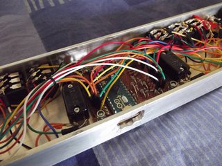
Believe it or not the hardest part of this was soldering the damn thing up! Case is made from 3inch by 1inch aluminium C section (1/8inch thick), which I milled/drilled at my old school's Design+Tech department (many thanks to them). Arduino programming was actually fairly straightforward, with the trickiest bit being getting the optoisolator (used to isolate the MIDI-in jack) to work because I kept wiring it up wrong on the breadboard. Total code is currently slightly over 800 lines, including comments, so really it's very manageable.

All in all, lots of fun building this little gadget - I'm very confident in its reliability and it'll be going with me next time I'm on stage! Would encourage you all to have a tinker with this sort of thing; I'd imagine the extra expression pedal/switch inputs alone could make one of these very useful to a large number of you :D

Pics of course - the LEDs are so bright that they actually threw the camera off focus on a few shots, but I think there's enough there for people to make things out. Schematic + code snippets etc will be available upon request :)


I love these DIY projects! Very well done!! :) Please keep up updated on your progress?
 
*bows* ta very much :)

Will keep updated but I doubt much will change now...

dgzieg - I have to admit that sadly I *did* have to super glue (well, araldite) the on-switch in place... and the hole in the frame behind the arduino's USB port is wonky/rough cause I forgot to mill it in D+T, and had to do it at home with hand tools... so not quite as perfect as I'd like it to be :D
 
Fantastic project and result. Congratulation !
As i built myself my own axe fx controller, i can fully understand how much work and préparation it needs both for coding/design and soldering/ wiring

I would be very interested in seeing your arduino code if you accept to share it with me.
My own project description + code is of course available for you or anyone interested (i precise that it is not an arduino based controller, but a midi CPU based one)
http://forum.fractalaudio.com/other...y-diyers-working-custom-foot-controllers.html
Post#15
 
Haha I'll neaten up the code and upload it in the near future then :) There's still a function or two that needs fleshing out but apart from that it's done. Also... when I designed it, I initially planned for the buttons to be the other way round (e.g. the "switch to clean" button, here on the left, was actually going to be on the right)... and it wasn't as easy as you'd expect to switch it all over, because some things (like the PC designation) had to stay in the correct order (1 on the left, 6 on the right)... so that kinda screwed over my code a little bit, fair warning to all who read it :D

manu - that controller looks awesome, you've definitely got the labelling down! I think I'm going to run out of room on mine... the LEDs look very snazzy on yours?

Paranoid - that's what's particularly good about the external switch inputs: I just give him the cheap, DIY equivalent of a Boss FS-6, and now he's got two switches for effects and clean... then he takes an expression pedal or two as well (seeing as four are available now if you use the input on the Axe II as well) and we're sorted!
 
Hi
Excellant job dude ,
any chance of sharing the wiring diagram as well as the programing code,
I have in the past changed pups in guitars and have no problem with soldering ,
but didn't have a clue where to start when it came to building a midi control board ,
so I decided to buy one,
now I have a bit of time it may be a future project if I can get my head around the programming side I may think an add on for the mfc

cheers
G \../
 
@grit
PM box is full.
I could send you a full description of my own project as soon as I can send a message :lol

I have just seen that the led are not installed in the pictures I posted.
There is of course pictures with Leds in my .pdf :mrgreen

(for anyone interested, my project .pdf is of course available . Just send me a PM if interested)
 
manu - inbox now has space, sorry about that :D yes please to the project description etc

waylander - yup, will share the wiring diagram when I put the code up. It was done in powerpoint (is made of autoshapes) so isn't *that* good/easy to read, but I can also provide little individual diagrams of all the individual circuits (protection, midi-in etc) so that you can see what's going on there :)

voes - I must thank you for your excellent documentation on the FCB1010 Uno mod - I would probably have been fairly stumped if it weren't for your help! Looks like the FCB will be delegated to backup duty now, though ;)
 
Wanted to do this with an Arduino for quite a while because I thought that it was a perfect platform for me to get my feet wet, but I never had time to invest into it and just bought the MFC101 (which is not a bad thing by the way).

Glad to see that someone else has done it and proved that it worked. :encouragement:
 
Wow!

What a cool project ! I've always thought it would be cool to have a "Mini MFC" type floorboard with a continuous controller and some bass / mid / treble / drive controls in a package I could fit in my Gigbag. The MFC is overkill (and a little pricy) for me. I currently use a Lexicon MPX-R1 which "kind of" works.....
 
Code and Wiring Diagrams

By popular request, I've neatened up the code and made some wiring diagrams for release to the general public :)

Arduino is coded in a slightly modified version of C - you can get my code from here, but will need to install the MIDI library from here first.

Wiring diagrams are in the pictures below - it's effectively a "picture" of a veroboard circuit, telling me where to cut and where to solder etc. The green horizontal lines are the vero lanes, the blue rectangles indicate a lane to cut, and then I think wires and resistors etc are pretty self-explanatory. Diodes and LEDs have the arrow pointing in direction of current flow when they're conducting.


Basic instructions for use of the controller (read this as you read the code, it'll probably help)

In Standby
  • Press/tap buttons 1, 2 or 3 to toggle Guitar 1's Clean, FX1 or FX2 respectively (CCs 100, 23 and 25; blue FX leds light up to indicate)
  • Hold button four to make expression pedal 1 send CC 11 instead of CC 24, to control the overall volume of the Axe. Tap again to turn off. Blue FX LED indicates.
  • Hold button five to engage tuner, sending relevant CC (see below)
  • Hold button six to enter Set Preset submenu (see below)
  • Expression pedals 0, 1 and 2 will normally send CCs 22, 24 and 18
  • External switches will send CCs 101 and 16 respectively, to control 2nd Guitarist's clean and FX
  • Hold buttons one and six to enter calibrate/setup submenu (see below)

Tuner
  • FX LED five will flash, along with all PC LEDs, until button five is released
  • If midi tuner sysex messages are received from the Axe, the readout will be displayed on the PC LEDs. Centre two LEDs on together indicates perfect tuning. If no sysex received, PC LEDs will just stay on solidly. FX LED will continue flashing
  • Tap button five to exit tuner

Set Preset
  • Current PC light will stay on solidly while all others will flash. Simply release button six, then choose your preset by pressing the equivalent button (button six is a possible choice)
  • Flashing will stop, chosen LED will stay on solidly

Calibrate Submenu
  • PC LEDs one and six will flash
  • FX LED 5 will indicate which "mode" you're in. Currently there are two modes (light on or off), though could extent program to scroll through PC lights 2 to 5, for example, giving four modes. In practice, there is only one mode of use of the footswitch currently, so this indicator doesn't really mean much
  • Press buttons 2, 3 or 4 to calibrate expression pedals 0, 1 or 2 respectively. Relevant FX LED will flash, then move the expression pedal through full range of motion. When finished, press relevant button again; flashing will stop and calibration will be stored to EEPROM (so that the pedalboard will remember the settings next time you switch it on)
  • Press buttons one or six to exit calibration mode


Wiring Diagrams - my "protection circuitry" consisted of a resistor to drop voltage across and limit current/absorb power; the diodes are used to "send" the voltage to the +5V or Ground rails, away from the analog pins, if the voltage is outside of the safe range (though there's a 0.7V gap due to the diodes themselves).
Buttons and Switches use analog pins to read the voltage; button input matches this to a lookup table to work out which button(s) has been/are pressed; switch input just checks if above a certain threshold. Switch LED is hardwired to avoid the need for another I/O pin on the Arduino (otherwise I wouldn't have had enough).

Imgur album is linked to the picture
 
Hi Grit,
Impressive mate.

Been working on my own DIY footcontroller for some time now too.
Using a Teensey 3.1. to control my AxeFX II.
Been learning as I go as only done VB before this project.

Got most of my initial goals working.
ie preset up/down.
Bank up/down,
Scene select (1 to 4).
Favourites Button (which allows toggling through my x number of fav presets using the preset up/down buttons).
Even recently managed to display Preset Name on my LCD by reading the get preset name sysex.

But have come up against a brick wall trying to read the Tuner Sysex.

I've just tonight stumbled across your postings so copied your section of code for reading the tuner sysex but get -

"Tuner_4.ino: In function 'void setup()':
Tuner_4.ino:75:44: error: invalid conversion from 'void (*)(byte*, unsigned int) {aka void (*)(unsigned char*, unsigned int)}' to 'void (*)(byte*, byte) {aka void (*)(unsigned char*, unsigned char)}' [-fpermissive]
In file included from Tuner_4.ino:2:0:
C:\Users\Medion\Documents\Arduino\libraries\MIDI/MIDI.h:231:7: error: initializing argument 1 of 'void MIDI_Class::setHandleSystemExclusive(void (*)(byte*, byte))' [-fpermissive]
void setHandleSystemExclusive(void (*fptr)(byte * array, byte size));
^
invalid conversion from 'void (*)(byte*, unsigned int) {aka void (*)(unsigned char*, unsigned int)}' to 'void (*)(byte*, byte) {aka void (*)(unsigned char*, unsigned char)}' [-fpermissive]"

Any ideas pls.

Also anything special in your MIDI IN circuit?
 
Back
Top Bottom