Hi ! Any pedal builders in there ? I will try to do my first one, wish me luck 

Last edited:
Good luck! It can be a very fun and rewarding hobby.Hi ! Any pedal builders in there ? I will try to do my first one, wish me luck
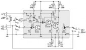
View attachment 113471
MusikdingWhich kit is that?

What's the part code on them? Figuring out which leg is the emitter and which is the collector depends on the part. Middle leg is the base.I’m learning components and how they work one by one , the thing that make me scratch my head are the germanium transistors , there is a way to plug them, not like the resistors but I don’t see a + and - . They are 3 « leg » and 2 solutions to plug them so . Hm. Why am I doing this ?
They are both ac125 , one got 4M on the top and the other HM , it is difficult to read . There is nothing more than I8V1 (?) on there but …What's the part code on them? Figuring out which leg is the emitter and which is the collector depends on the part. Middle leg is the base.
Does it have a metal tab sticking out of the edge of the package? If so, the leg closest to the tab is the emitter.They are both ac125 , one got 4M on the top and the other HM , it is difficult to read . There is nothing more than I8V1 (?) on there but …
!!! Yes there is !Does it have a metal tab sticking out of the edge of the package? If so, the leg closest to the tab is the emitter.

Also we are ok that these are « + » ?Does it have a metal tab sticking out of the edge of the package? If so, the leg closest to the tab is the emitter.


Those spots are for capictors. They have two legs. And the must be oriented correcly for them to charge and discharge correctly. One of the legs will have a mark near it, or be longer, etc. Something to help you figure out which leg is the positive terminal and which is the negative terminal side of the capacitor. How you figure that out depends on the type of capacitor: https://www.electronics-tutorials.ws/capacitor/cap_2.htmlAlso we are ok that these are « + » ?
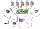
Sorry I’m really a beginner at this , I try to eliminate all my questions before starting anything View attachment 113495
Yes but you see in the pcb there is a half « + » in the location of the capacitors, I just wanted to be sure that is was a « + » . The included capa got the - on them with luckThose spots are for capictors. They have two legs. And the must be oriented correcly for them to charge and discharge correctly. One of the legs will have a mark near it, or be longer, etc. Something to help you figure out which leg is the positive terminal and which is the negative terminal side of the capacitor. How you figure that out depends on the type of capacitor: https://www.electronics-tutorials.ws/capacitor/cap_2.html
I “think” those are pluses, it looks like the solder points went over the markings when they made the PCB? If you are able trace the routing of the PCB on the other side, you may be able to locate where those components are on the schematic and confirm polarityYes but you see in the pcb there is a half « + » in the location of the capacitors, I just wanted to be sure that is was a « + » . The included capa got the - on them with luck