Larry Kehl
Inspired
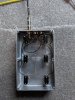
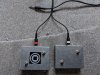
Just a suggestion, and you probably already looked at the topology but if you do build such a box and it is to be used in gig situation not just "home" then I would OFFSET the the three pots like this:
- Left and right pots (volume and echo feedback in your example) to the furthest upper left hand corner of the box and upper right hand corner respectively (both as close to edge as possible.
- Then the center pot (echo volume in your example) in the center lower edge as close to edge as it can be installed.
Don't forgot to allow for three TRS jacks (one per pot) someplace on back or each side or... wherever you want them.
With this config you can use a smaller project box then I did and when using your feet to adjust pot X there is less chance of moving the other two pots. Also you could probably, if desired, use those Wingman knobs without any between pots interferenace. Actaully those Wingmen knobs do look easier to use with a shoe'ed/booted foot.
Given the above config is not as aesthetically pleaseing as a uniformly spaced set of pots but IMHO a lot more pragmatic. As I mentioned above, somewhere, the reason I didn't exactaly was becasue I also wanted all four stand-in switches in same project box - so top row edge was already accounted for by those momentary switches
Good luck and if you do build one love to see a pic (I haven't acid etched anything since I quite making my own project PCB's)

 What he said