Frank L.
Member
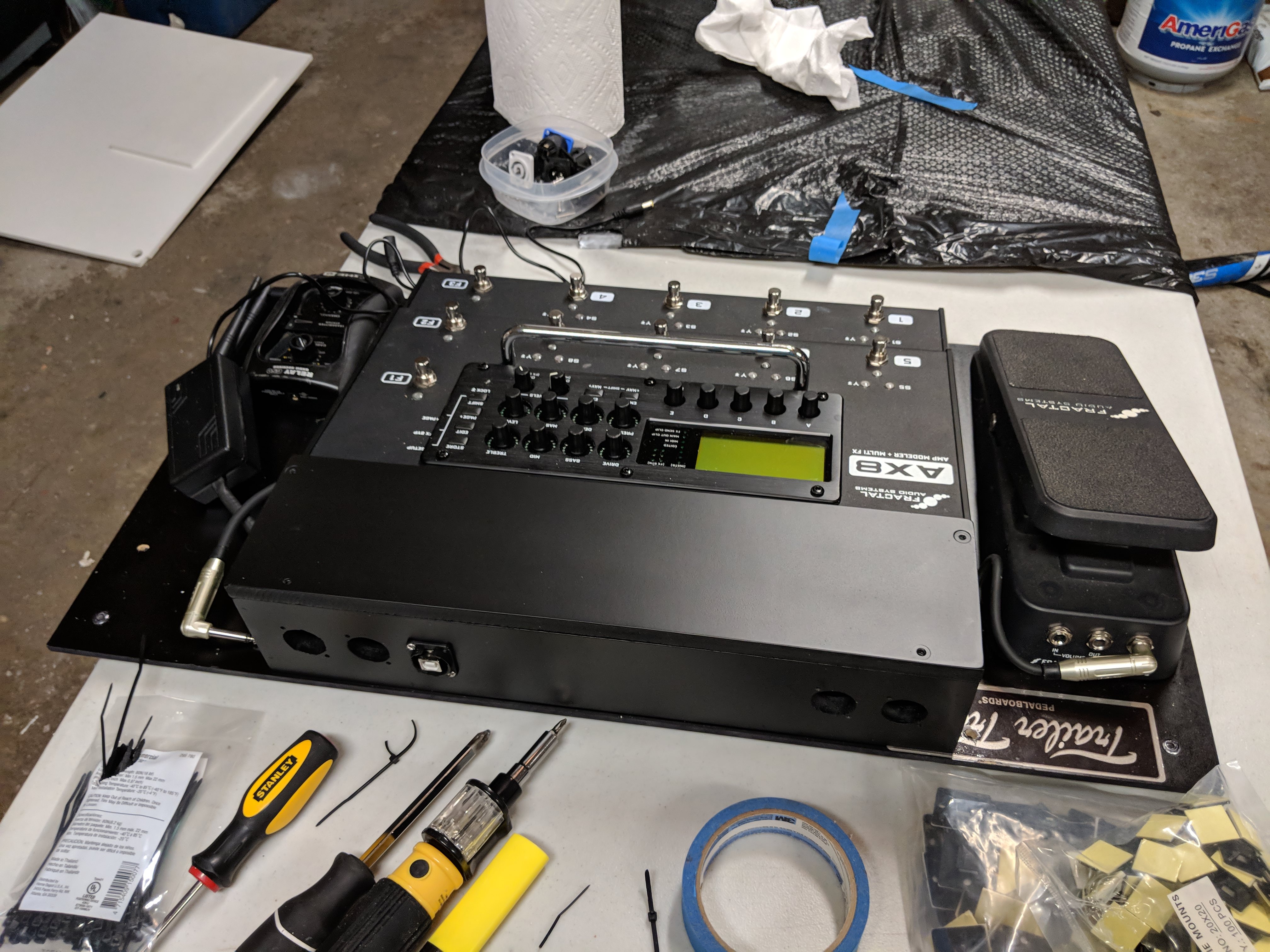
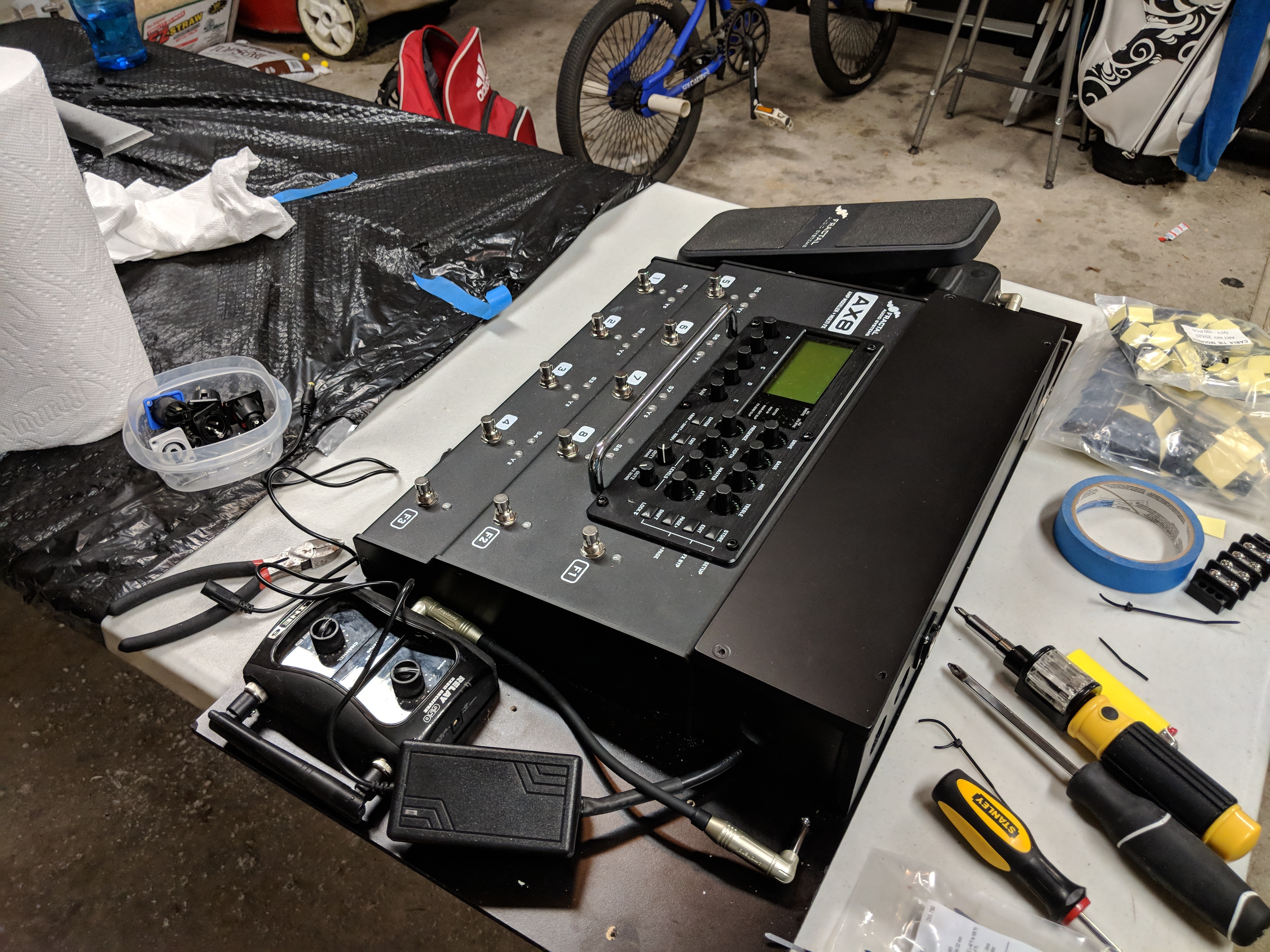
So I'm a huge fan of making things myself. After recently switching over from the FX8 to the AX8, I knew I needed to redesign my board a bit. There were a handful of goals in mind when starting this build:
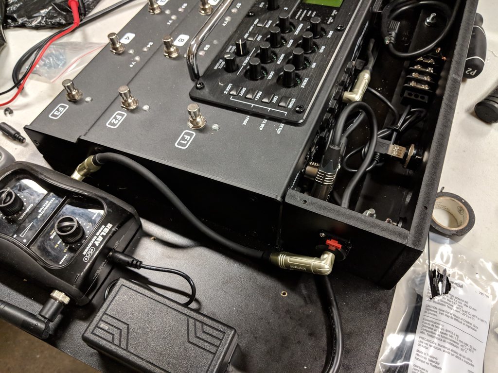
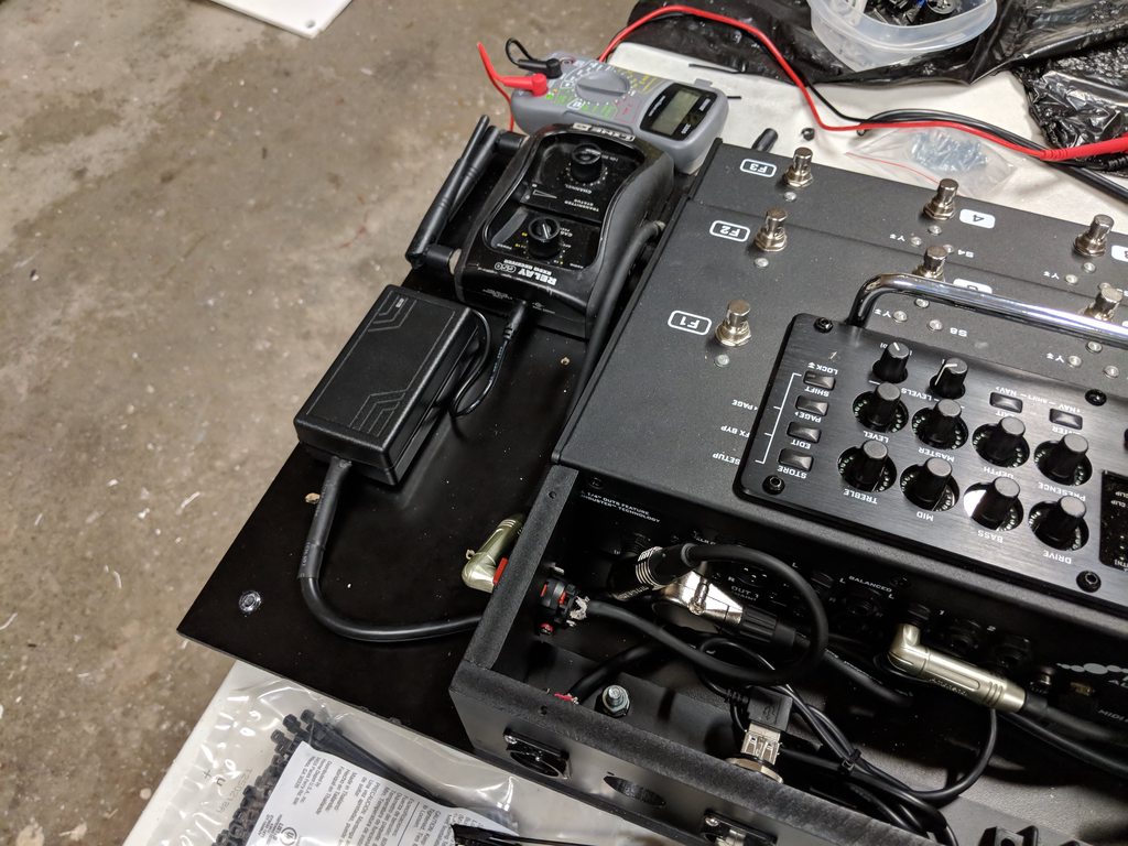
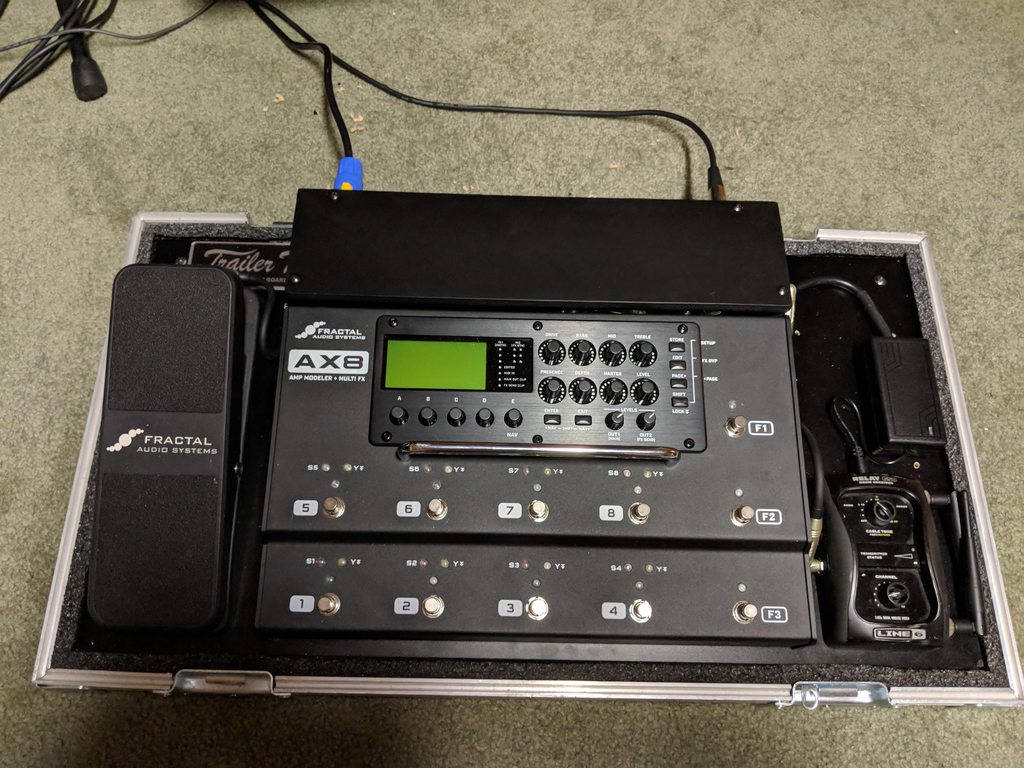
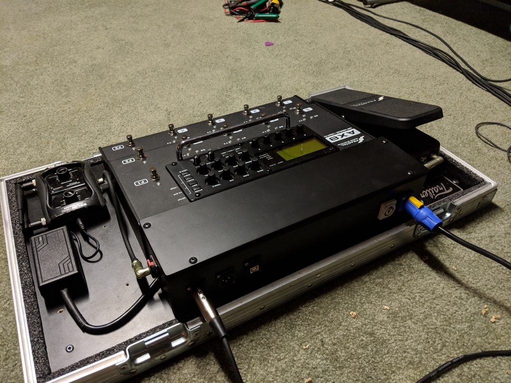
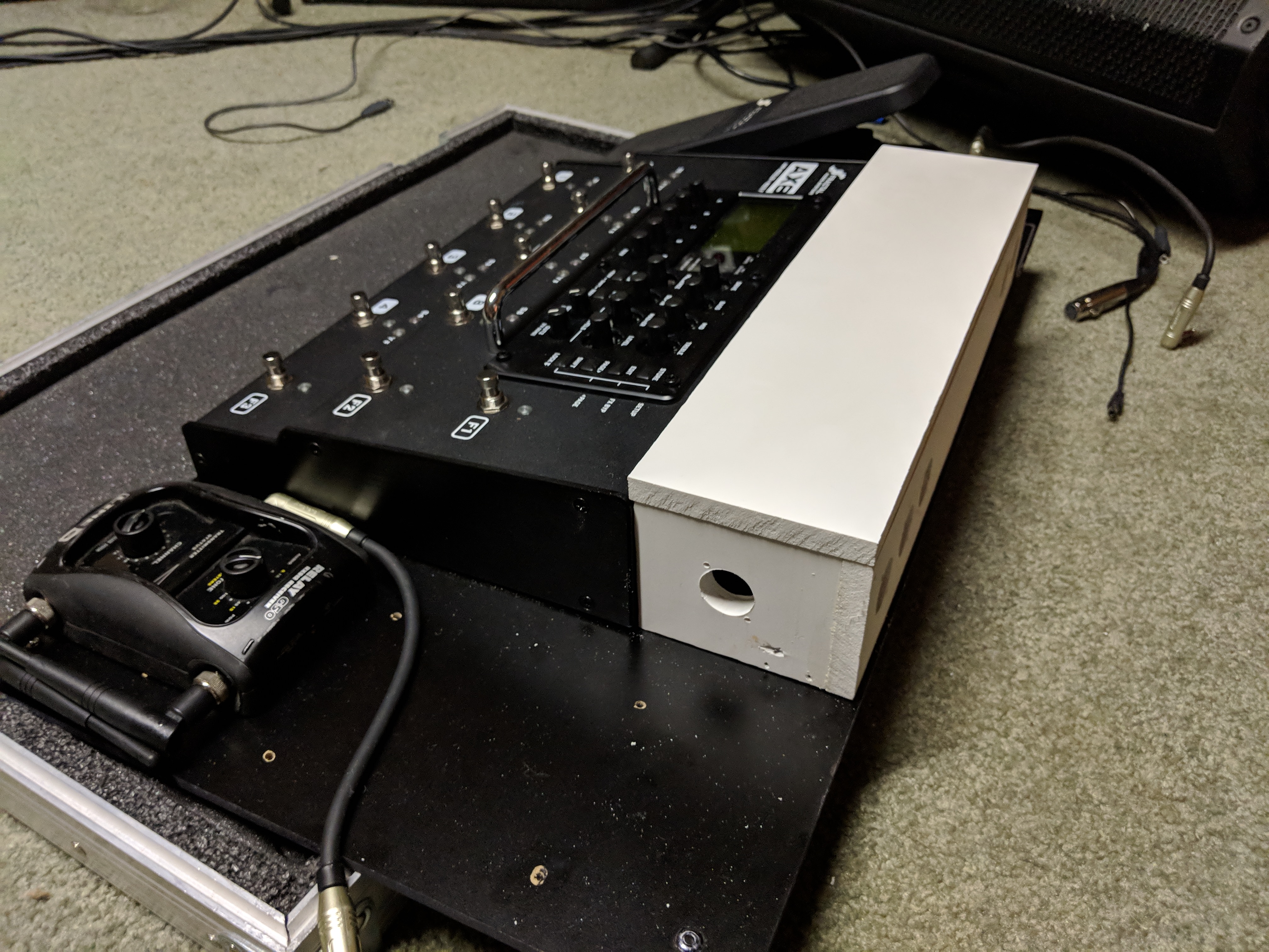
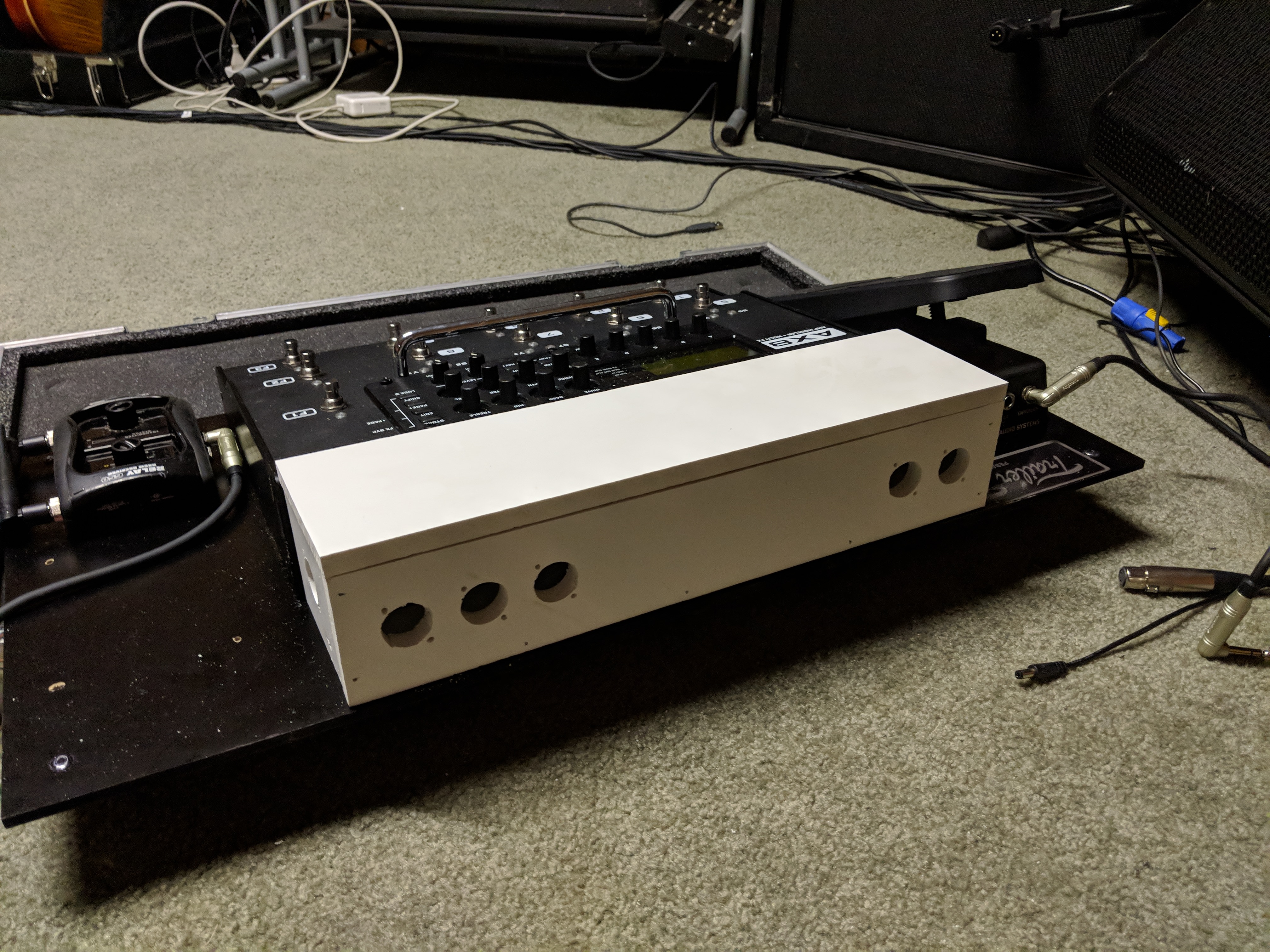
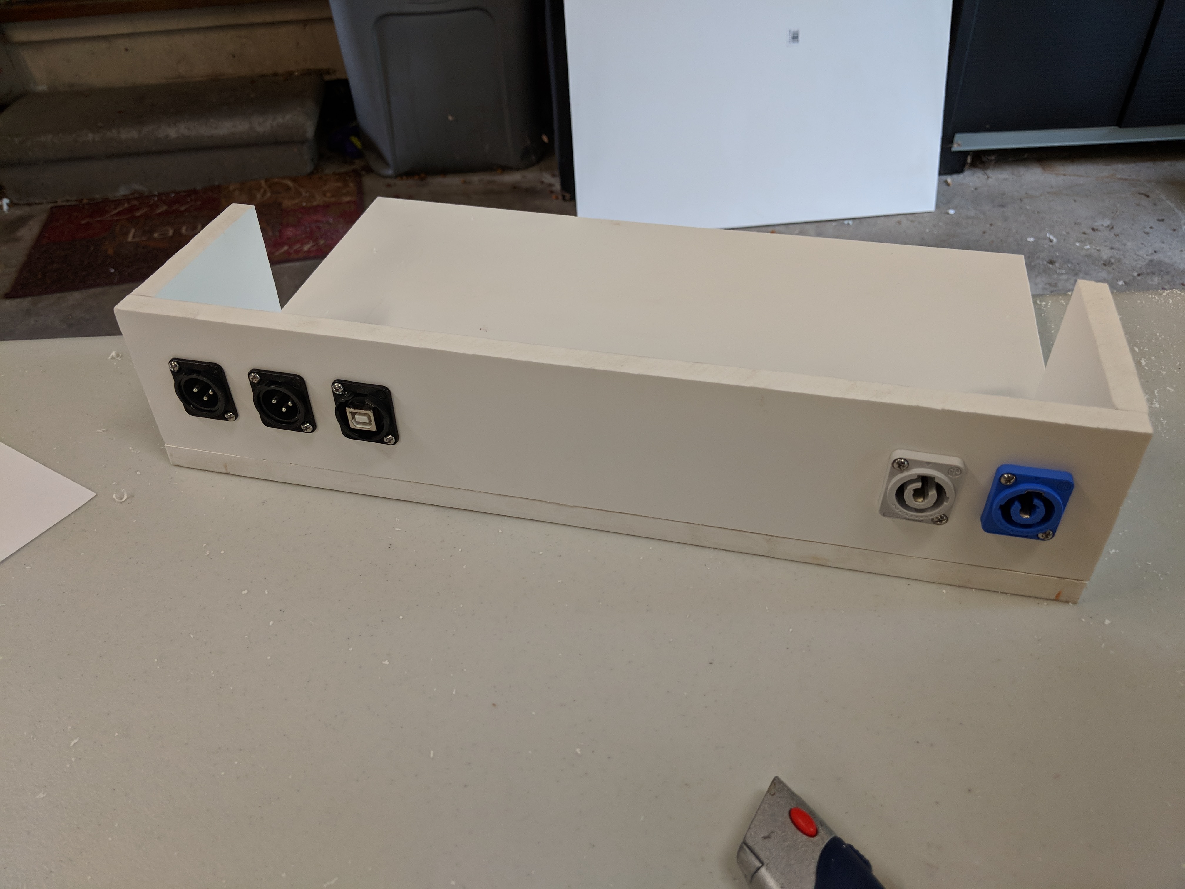
That being said, this is why I came up with. I just finished painting yesterday and started the mounting and wiring process. Obviously not complete yet, but wanted to show the progress thus far. The project started with a TrailerTrash board that is custom designed for the AX8/FX8 and 2 expression pedals. I never really needed 2 expression pedals, so I got rid of one of them to make room for my wireless.
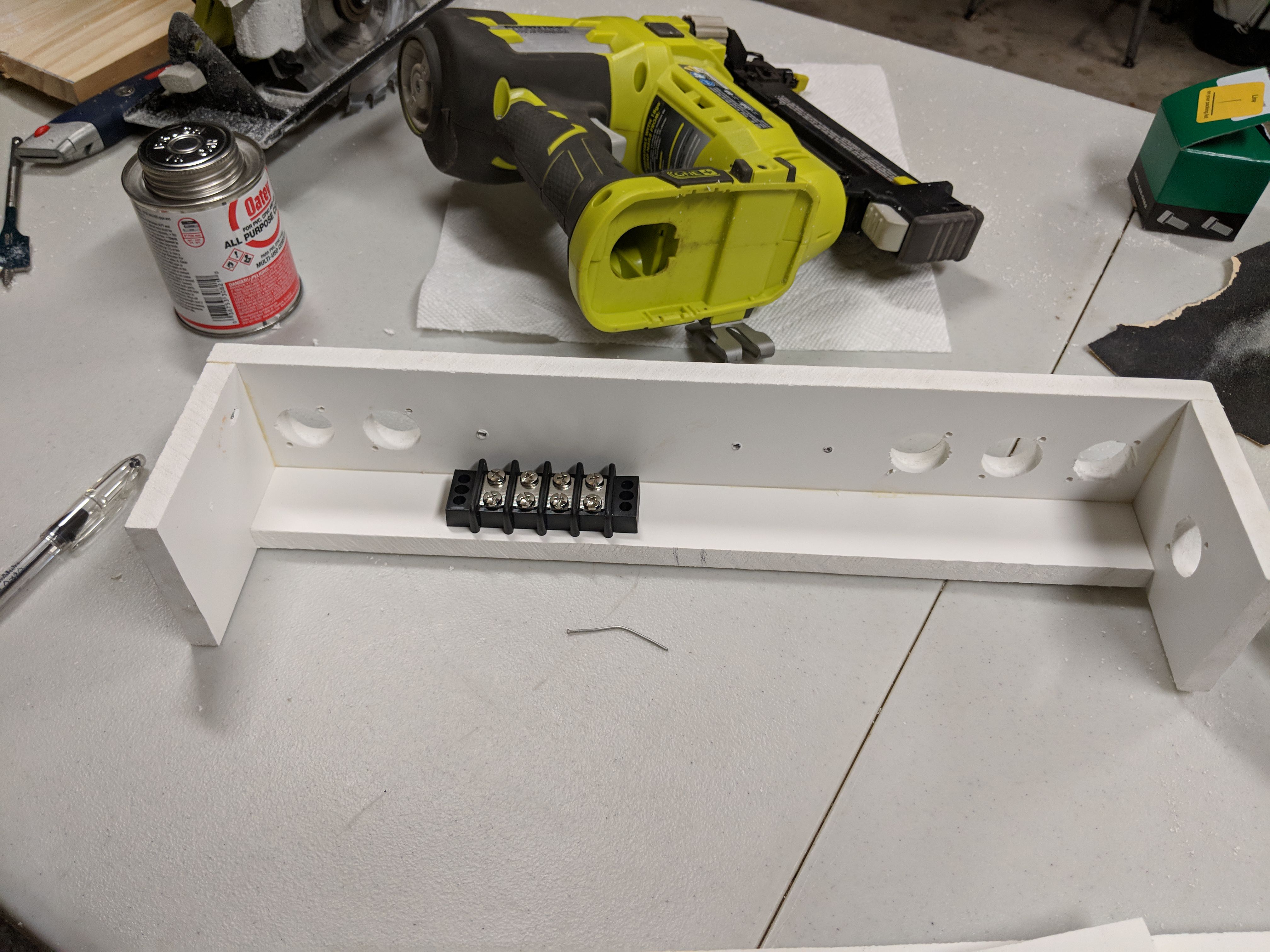
I use 1/2" Cellular PVC for this build. I wanted something a bit smoother than wood, and this fit the bill. The cut edges are a bit rougher than I wanted, but overall it looked pretty good after paint. Everything is held together with a combination of clear PVC cement and brad nails. A couple of the brads came out the side, mostly due to my own impatience. But I cut off the excess and filled them with plastic filler. After paint you can hardly see them.
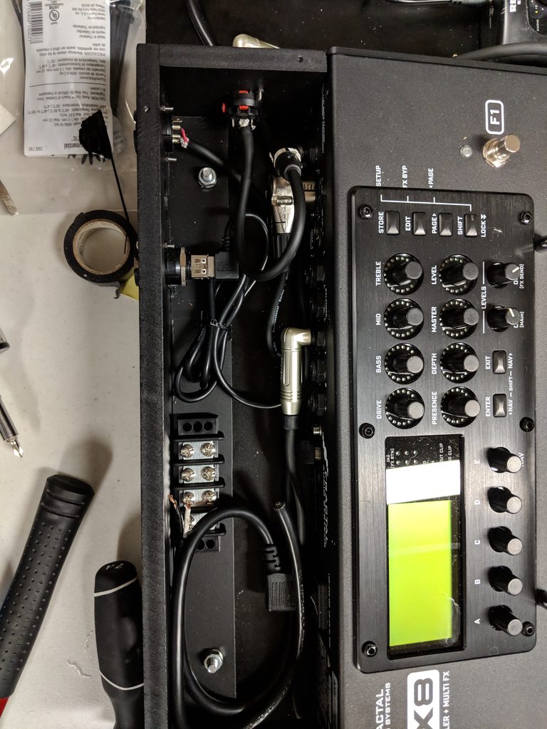
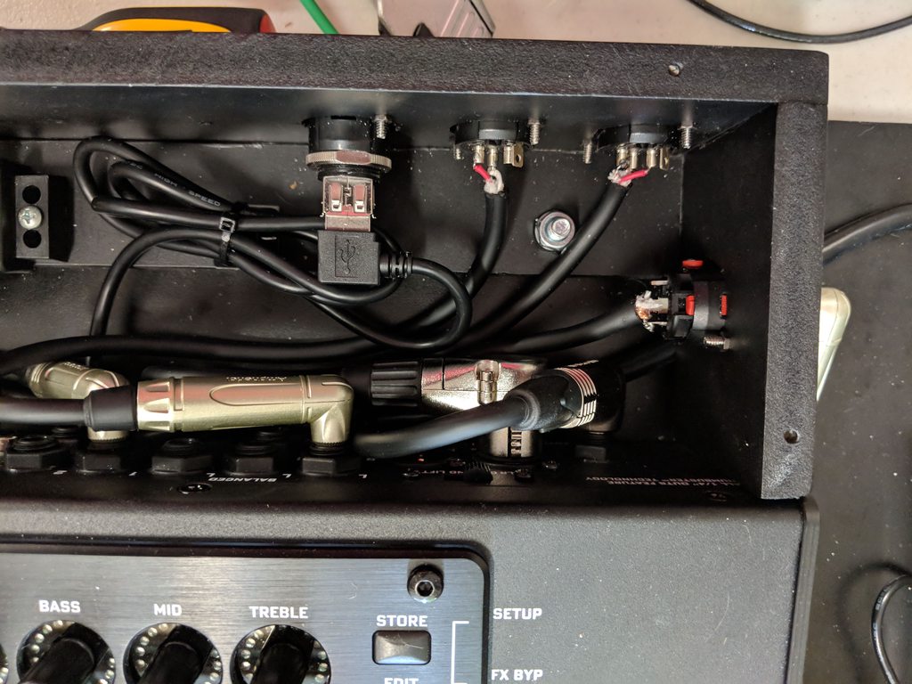
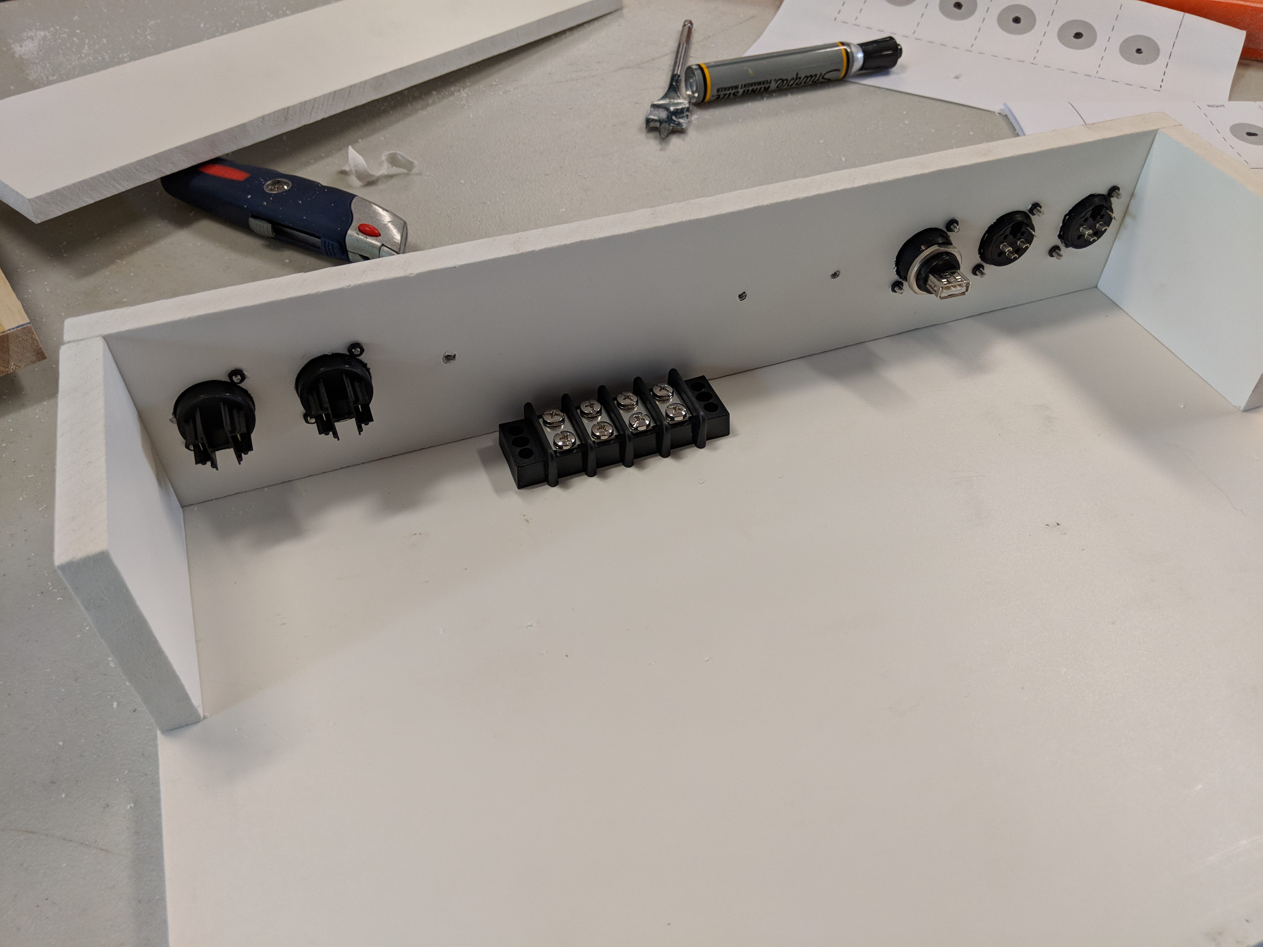
The holes to fit the D-series jacks were drilled with a 15/16" drill bit. I actually built a template using Adobe Illustrator on my computer in order to get them centered and aligned. I put a center "dot" on each hole. Once it was complete, I printed it out (in 2 sheets, left and right), and punched out the dot in the middle of the holes on my sheet. I then lined up the edges to my boards, and used a sharpie to mark the center of the holes. Once that was there, it was easy to drill the holes perfectly. You'll also notice I "marked" some of the other holes, so if I decide to add additional jacks later, I have the holes already setup.
I did a 3 stage painting process. First, I sanded all surfaces using 300-800 grit sandpaper, smoothing over some of the edges in the process. Next, I applied acetone to the PVC in order to give the pain something to stick to. I applied a bit more acetone on the cut edges as it helped to smooth things out a bit (it literally melts the plastic). Lastly, I applied 4 coats of Flat Black spray paint that is made for plastics. I dont recall the brand offhand, but if anyone is curious I'll post it up when I get back home.
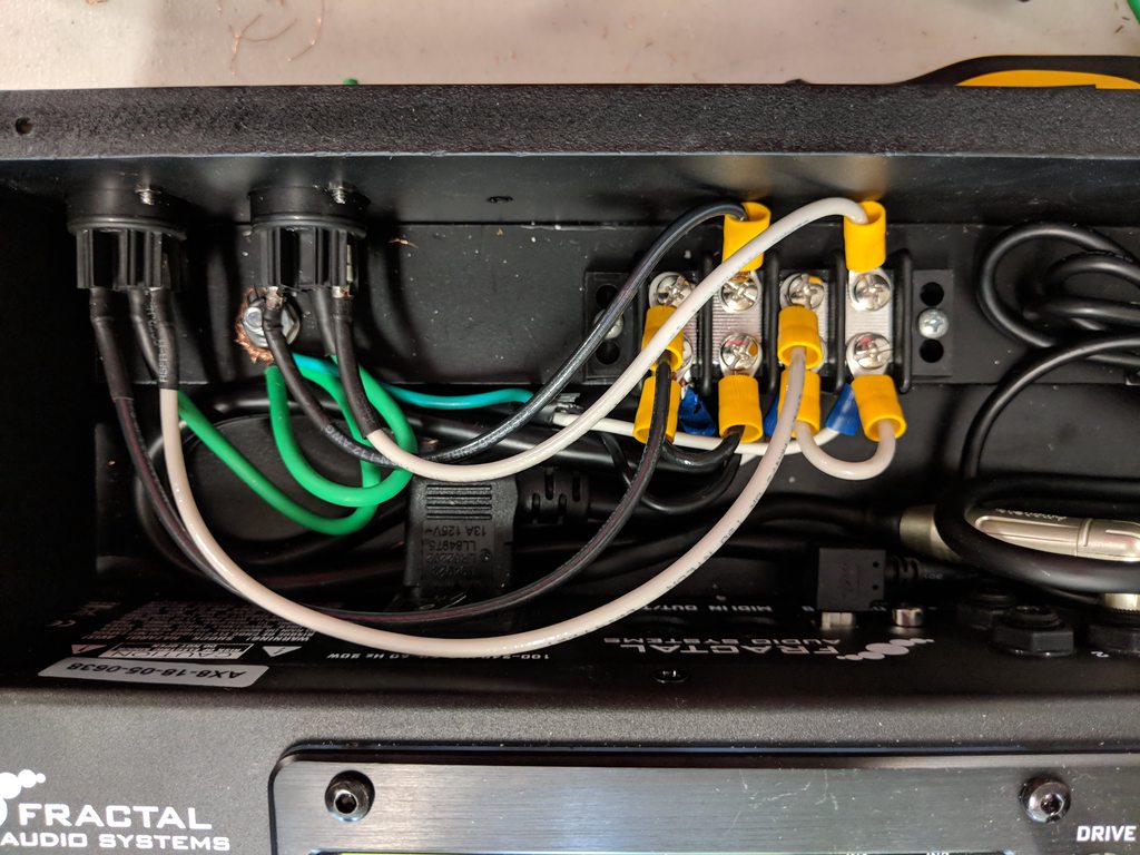
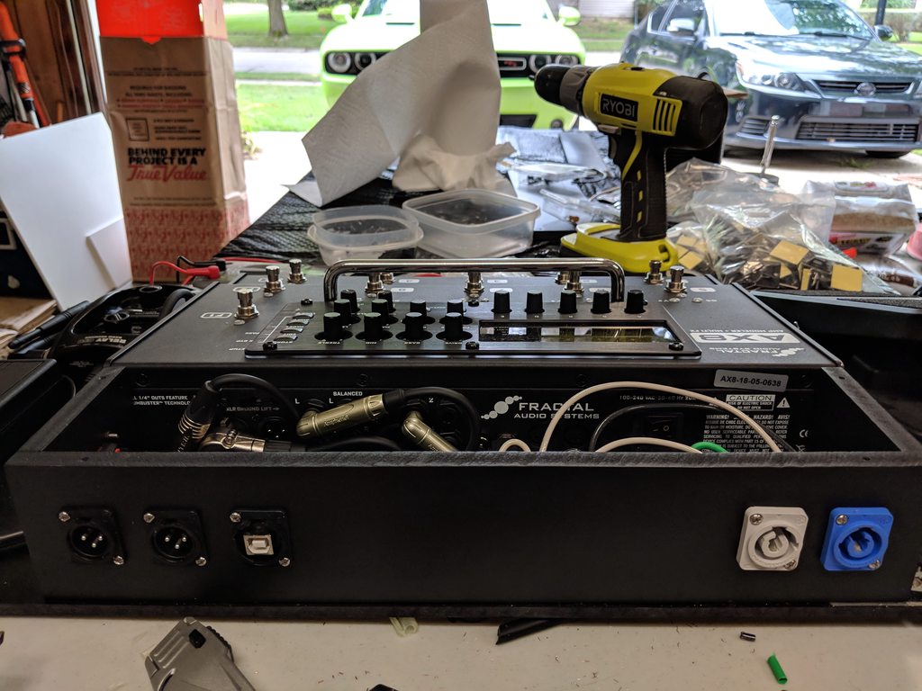
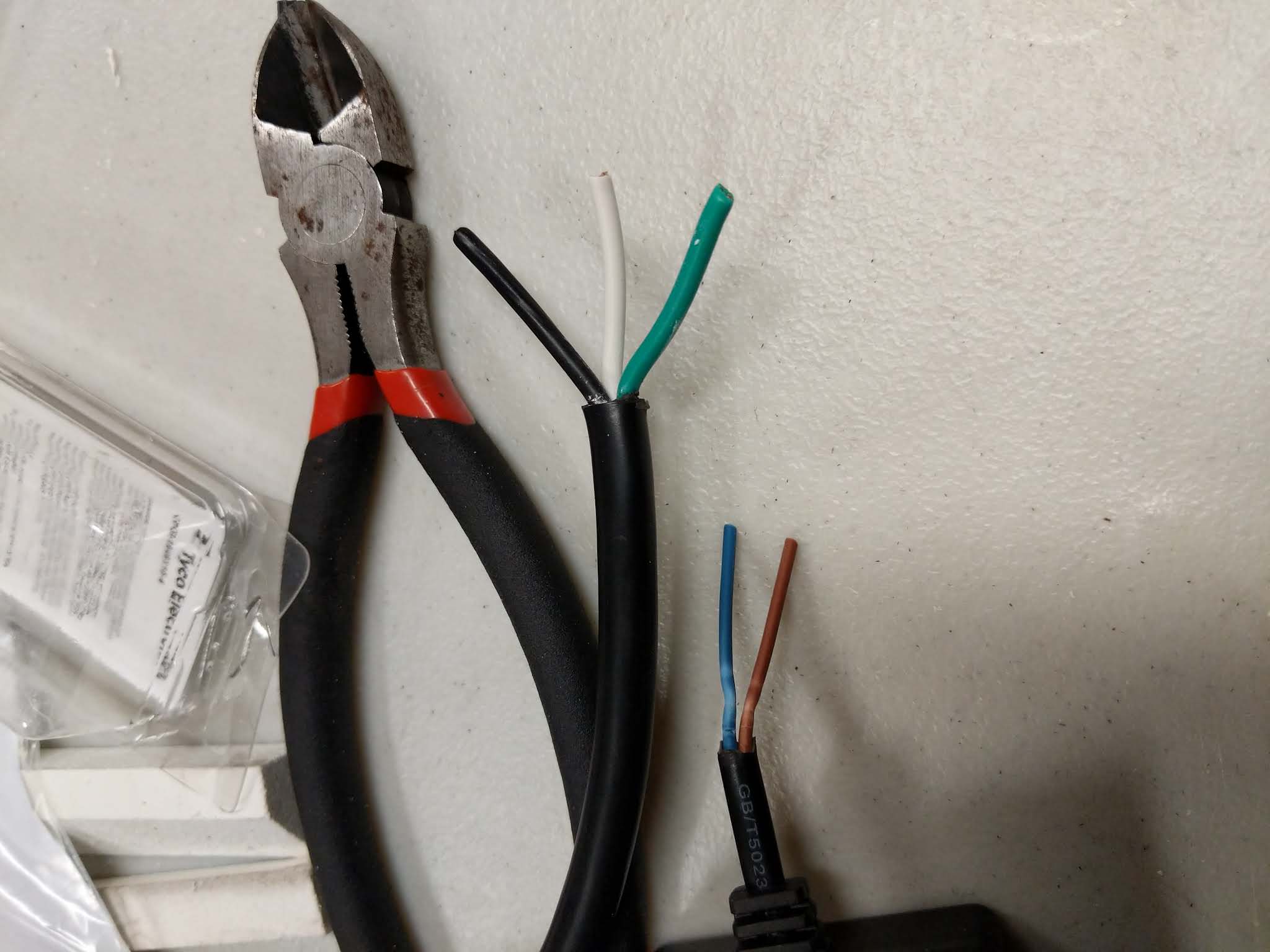
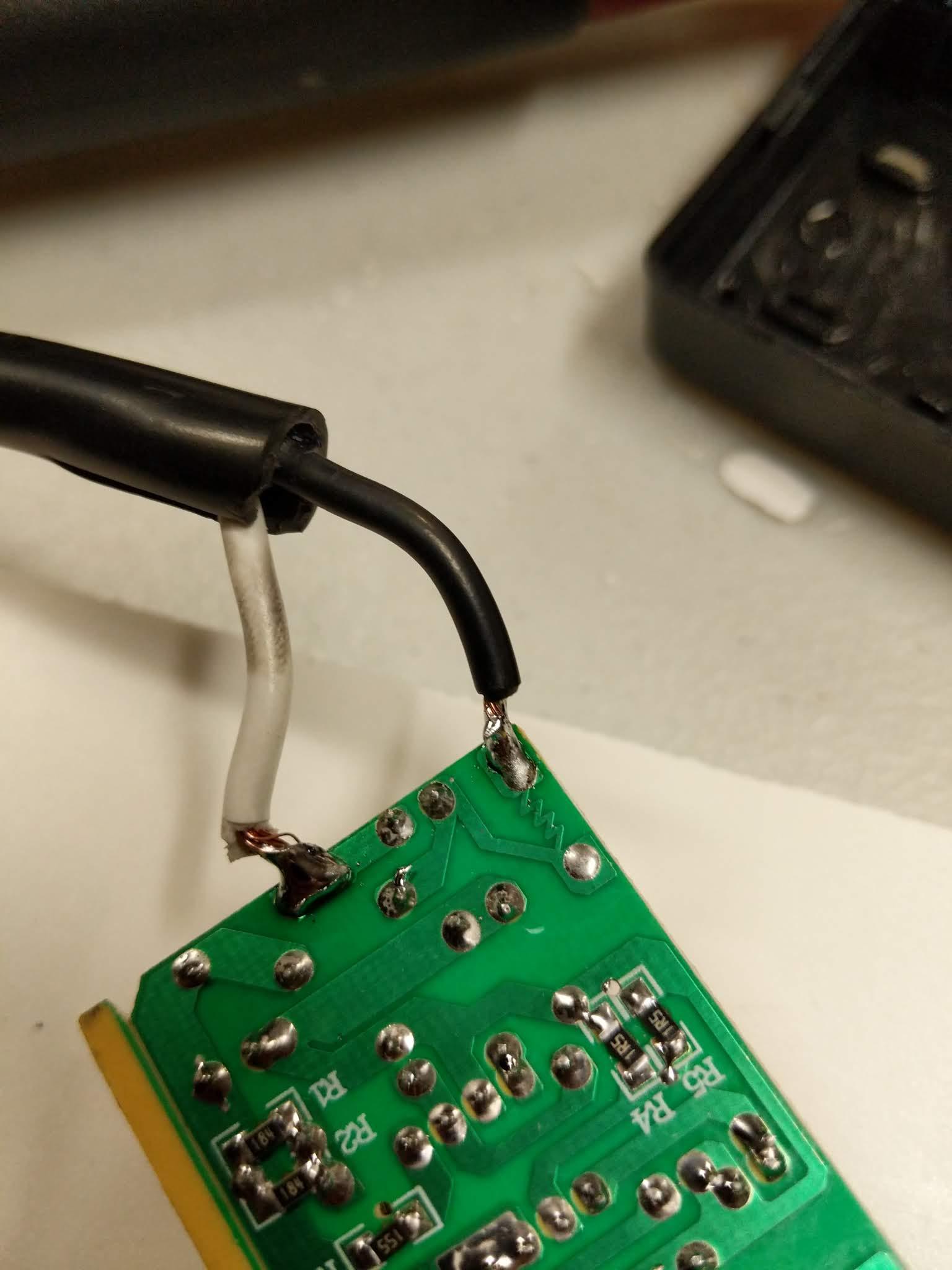
I planned on hard wiring everything into a distribution block, and then to the powercon-in jack. This posed a problem for my Line6 G50 wireless unit. It had a "wall wart" type of plug, so it wouldn't work in this application. To get around that, I found a compatible AC adapter that wasnt a "wall wart" type. However, the construction was a bit shoddy, and the power cable was thin and too short for my needs. Nothing a screw-driver and hammer couldnt resolve! I removed the casing from the AC adapter, desoldered the old AC plug, and soldered in a heavy duty (16ga) cable. I also plan on shortening the 9V side of the adapter so I do not have a bunch of extra cables.
Anyways, Thats where I'm at. I'll post up some more pictures as I get further with the build. But I'm super-happy with how its turning out.
And now.. For the pictures!
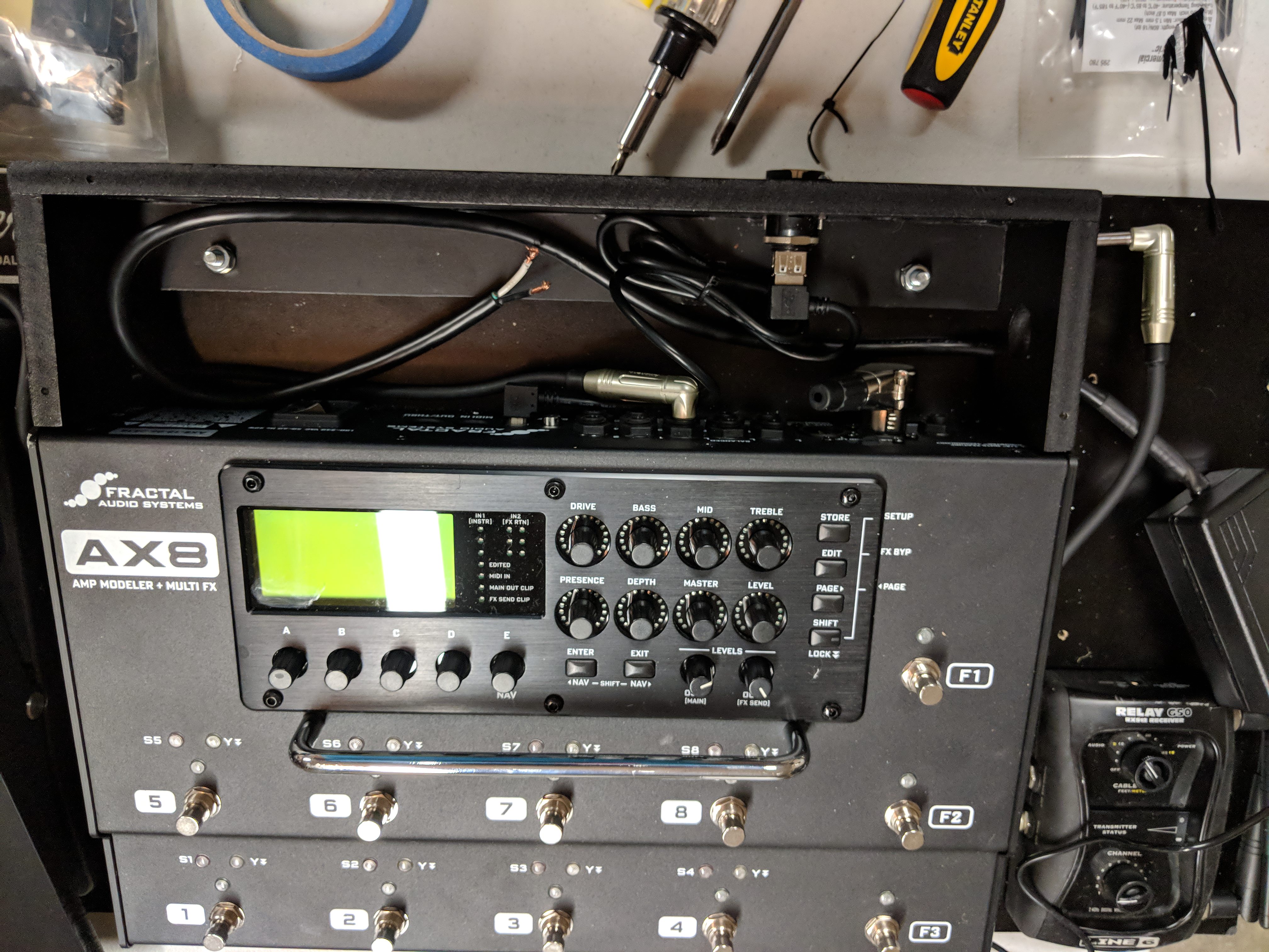
- I wanted to move my wireless to the pedalboard (use to be in the backline)
- Only 1 power cable would connect to the board (Powercon)
- I would have a powercon outlet to connect my stage monitor(s)
- Have the ability to expand to stereo if needed in the future.
- Have the ability to jack in a regular guitar cable in case of wireless failure
That being said, this is why I came up with. I just finished painting yesterday and started the mounting and wiring process. Obviously not complete yet, but wanted to show the progress thus far. The project started with a TrailerTrash board that is custom designed for the AX8/FX8 and 2 expression pedals. I never really needed 2 expression pedals, so I got rid of one of them to make room for my wireless.
I use 1/2" Cellular PVC for this build. I wanted something a bit smoother than wood, and this fit the bill. The cut edges are a bit rougher than I wanted, but overall it looked pretty good after paint. Everything is held together with a combination of clear PVC cement and brad nails. A couple of the brads came out the side, mostly due to my own impatience. But I cut off the excess and filled them with plastic filler. After paint you can hardly see them.
The holes to fit the D-series jacks were drilled with a 15/16" drill bit. I actually built a template using Adobe Illustrator on my computer in order to get them centered and aligned. I put a center "dot" on each hole. Once it was complete, I printed it out (in 2 sheets, left and right), and punched out the dot in the middle of the holes on my sheet. I then lined up the edges to my boards, and used a sharpie to mark the center of the holes. Once that was there, it was easy to drill the holes perfectly. You'll also notice I "marked" some of the other holes, so if I decide to add additional jacks later, I have the holes already setup.
I did a 3 stage painting process. First, I sanded all surfaces using 300-800 grit sandpaper, smoothing over some of the edges in the process. Next, I applied acetone to the PVC in order to give the pain something to stick to. I applied a bit more acetone on the cut edges as it helped to smooth things out a bit (it literally melts the plastic). Lastly, I applied 4 coats of Flat Black spray paint that is made for plastics. I dont recall the brand offhand, but if anyone is curious I'll post it up when I get back home.
I planned on hard wiring everything into a distribution block, and then to the powercon-in jack. This posed a problem for my Line6 G50 wireless unit. It had a "wall wart" type of plug, so it wouldn't work in this application. To get around that, I found a compatible AC adapter that wasnt a "wall wart" type. However, the construction was a bit shoddy, and the power cable was thin and too short for my needs. Nothing a screw-driver and hammer couldnt resolve! I removed the casing from the AC adapter, desoldered the old AC plug, and soldered in a heavy duty (16ga) cable. I also plan on shortening the 9V side of the adapter so I do not have a bunch of extra cables.
Anyways, Thats where I'm at. I'll post up some more pictures as I get further with the build. But I'm super-happy with how its turning out.
And now.. For the pictures!
")