I can also dig out all the formulae from the RCA Radiotron Designer's Handbook to prove it to you with math, too.
The math. Apologies to you who are about to suffer my handwriting - I don't have a fancy program to graph this stuff.
Analysis ignores the volume pots and tone pot, and simply focuses on the coupling of the two cathodes and the low/low-mid output at the plate of the channel you are
not plugged into.
Terms:
Triode #1 is the channel your guitar is plugged into.
Triode #2 is the channel your guitar is
not plugged into.
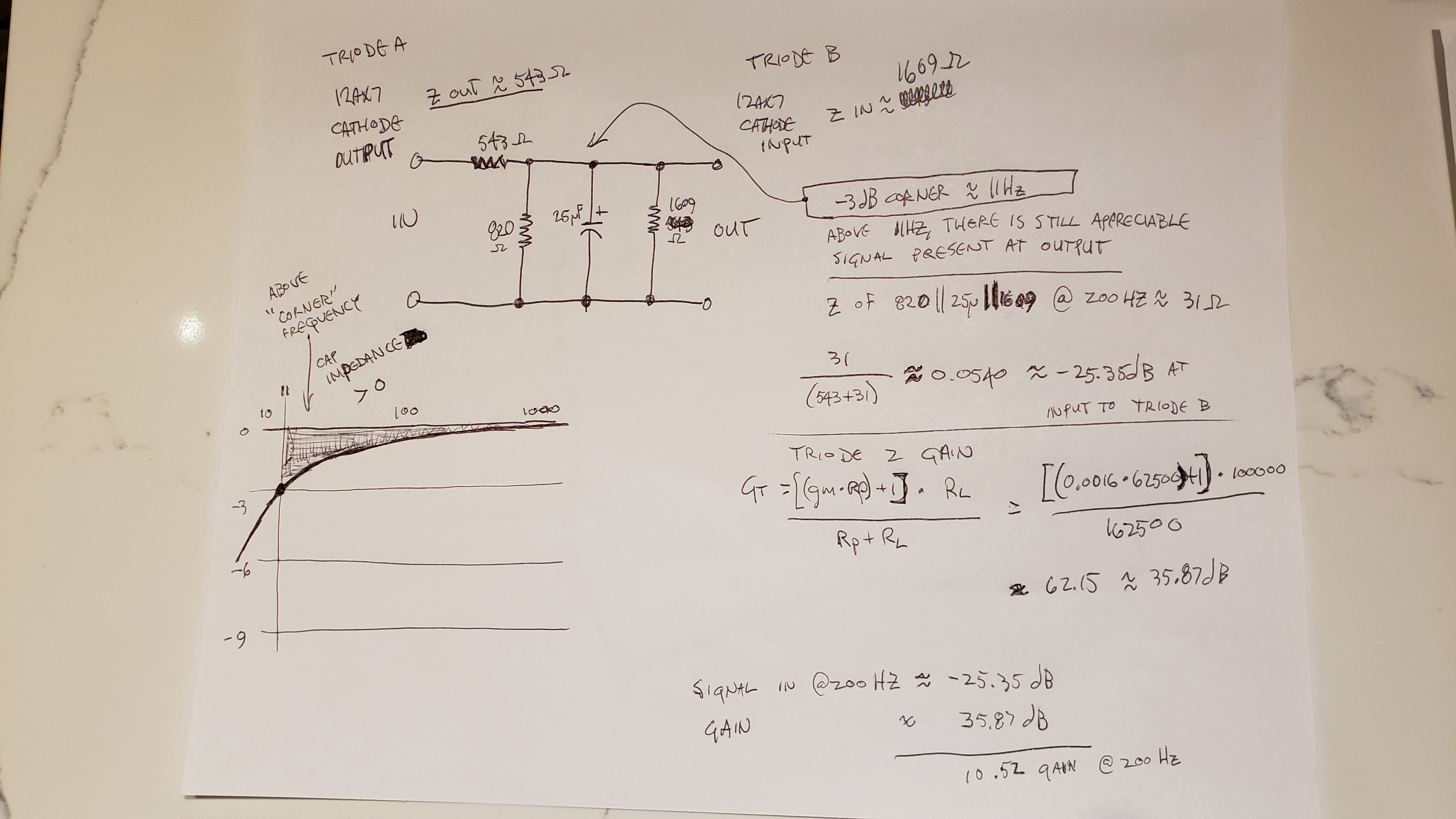
The equivalent circuit at top left shows what is going on when Triode #1's cathode drives Triode #2's cathode in this circuit, with the 820 ohm and 25uF shared cathode resistor/cap, as well as the output impedance of Triode #1's cathode and the input impedance of Triode #2's cathode. The doodle in the lower left shows what "corner frequency" really means - i.e., where the slight drop-off turns the corner and becomes a straight -6dB/8va drop-off. Shown in the doodle is an 11Hz corner frequency. Nearly flat for all frequencies in the audio band, and certainly the triode's cathode resistance is nearly 100% bypassed at guitar frequencies, for the purposes of calculating Triode #1's audio gain.
I show the calculations gain of a common-grid 12AX7 stage, about 62.15 or 35.87dB.
I also show the calculations at 200Hz for the gain lost due to the cathode resistor in parallel with Triode #2's input impedance and the 25uF cap. The impedance of the cathode resistor, cathode cap, and input impedance of Triode #2's cathode all in parallel form the lower part of the voltage divider with the output impedance of Triode #1 as the upper part, and this cuts the amount of signal applied to Triode #2's input by about -25.35dB at 200Hz. Calculations for 20Hz, 60Hz, and 600Hz are similar with differing dB losses, and the cap's impedance dominates the gain loss calculation.
I only show the 200Hz gain for the calculations on the above page. I was getting writer's cramp by this point as I don't write very often these days.
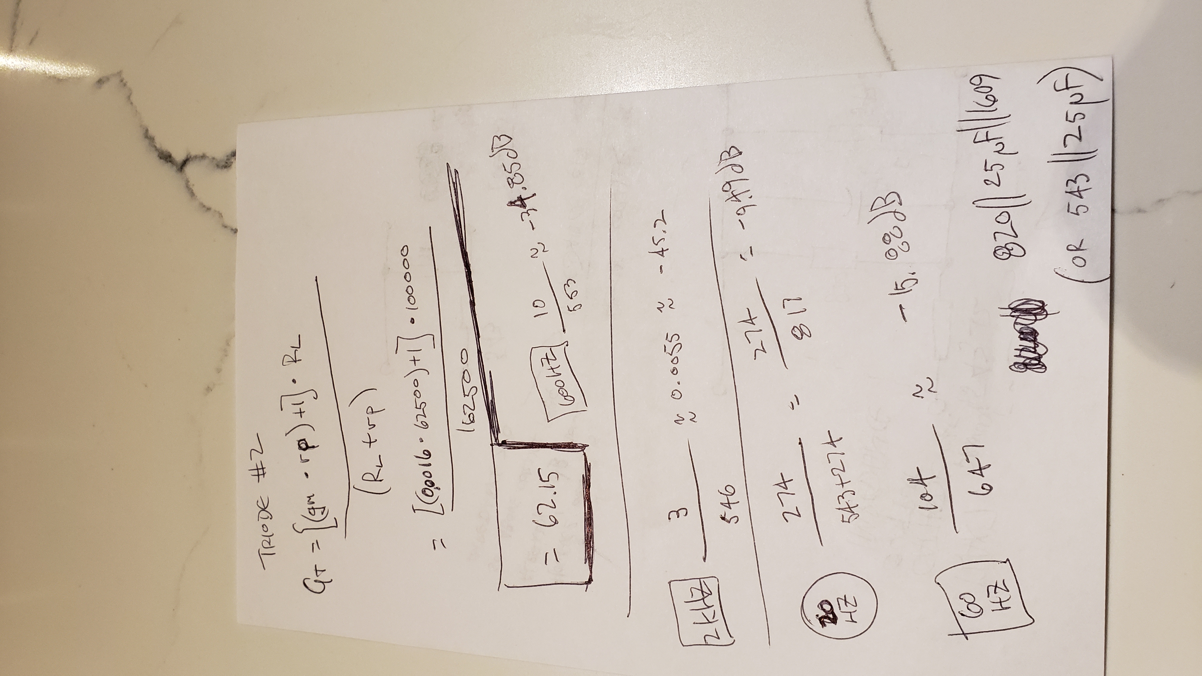
The following pic shows this value along with the remaining 20Hz, 60Hz, and 600Hz gains:
Gain at 20Hz at the "unused" channel's plate: 26.38dB, only about 8dB less than the gain in the stage you're plugged into.
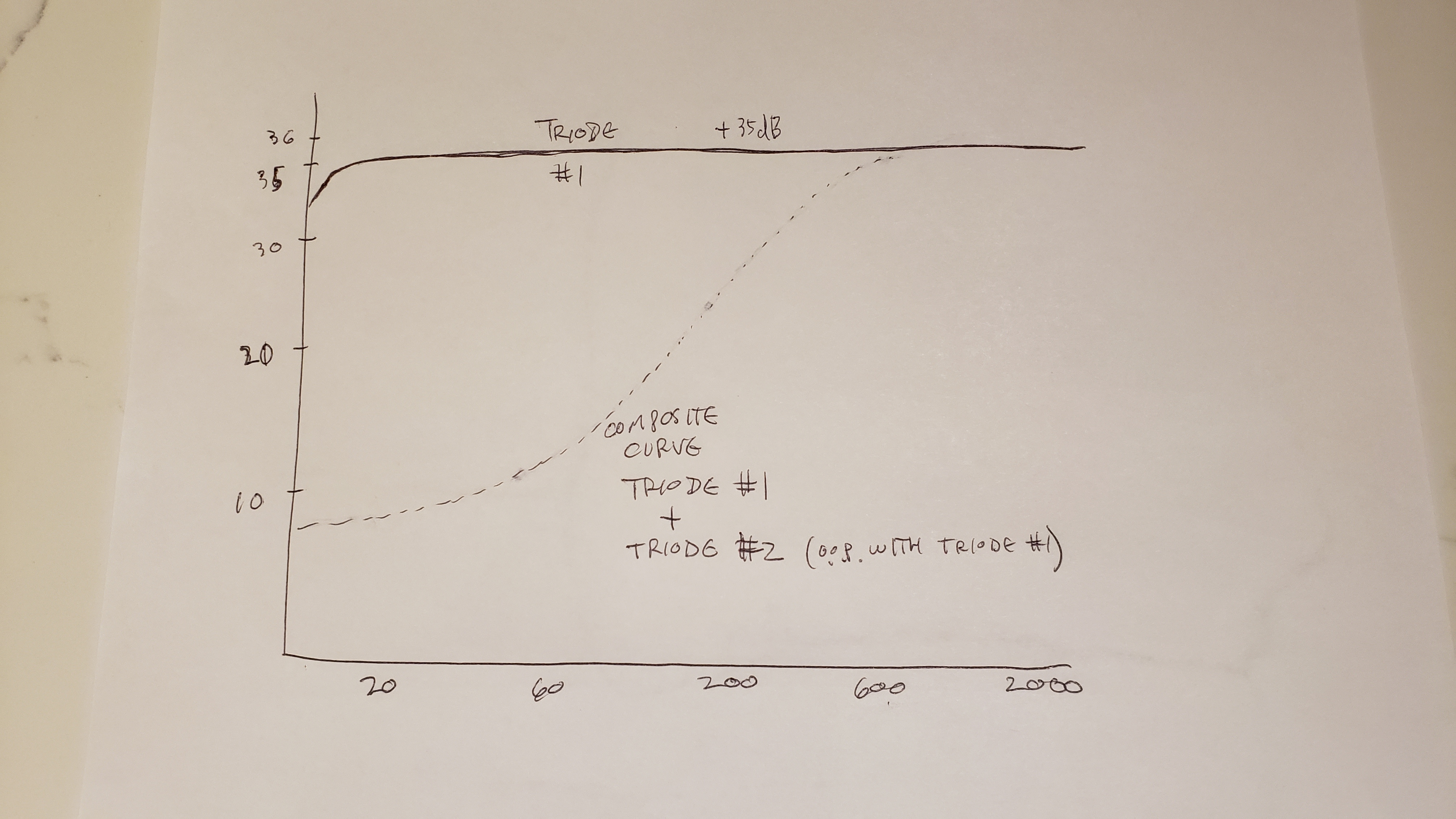
The below graph is a drawing of the one the nice common-cathode triode calculator drew for me after it did all the calculations for that for me. These type of circuits are common, and calculators for them are as well. I superimposed the first graph onto this one, and subtracted the output of Triode #2 from Triode #1, which shows the cancellation in the lows/low-mids at its maximum, as when the "unused" channel volume is full up. As the common-grid stage is non-inverting while a common-cathode stage is inverting, the resulting mixture is not additive, but subtractive. So, that nice 35dB gain gets a lot subtracted from it at lower frequencies. A far-from-insignificant amount of destructive interference is going on. Mind you, this neglects the mixer circuit formed by the two volume knobs, as well as the tone knob and the caps that make that work, and solely focuses on the plate output of the two triodes. Once you mix these two opposing-phase copies of the guitar signal with the three knobs, you get varying amounts of cancellation down low. As demonstrated in my video above, turning up the "unused" channel trims a significant amount of lows and low mids from the signal....
My calculations for the Triode #2 (unused channel) gain, and the various dB losses from the cathode cap to the signal driving Triode #2:
For you who like to look at the "scratch paper" as well. I used a handy online RC parallel impedance calculator for the impedance calculations, to save some time.
Sorry it's sideways. My phone sometimes does that to pics.
EDIT:
I noticed a wrong value in the calculation for Triode #2 gain - 1600uMho should be 1250uMho (I misremembered the value from the sheet instead of looking it up), for a gain of about 48, or 33.62db. Please subtract approximately 2.2dB from the entire curve for Triode #2's graph. Concept is the same, just a little bit milder effect than originally calculated.
Edit #2:
In the calculation of total gain of Triode #2, I forgot to include that the signal at Triode #1's cathode is less than the input signal. This affects the loss when recombining at equal volume control settings. When mixing the volumes per the settings in the video (and many "how to get the best out of your 5E3" instructions found on the web), the Triode #1 volume control is set a fair amount below noon, while Triode #2's is generally above 3 o'clock, which helps make up for the small signal out of Triode #1's cathode and causes a frequency response curve much like my drawing above when combined, as was demonstrated in my video. Mea culpa.